
Pad printing machine

a pad printing machine and pad printing technology, applied in printing presses, rotary presses, printing presses, etc., can solve the problems of inaccuracy of printing and limited printing speed of pad printing machines, and achieve the effect of preventing or preventing the pivoting or displacement of pads

Inactive Publication Date: 2012-03-29
TAMPOPRINT
View PDF6 Cites 0 Cited by
  • Summary
  • Abstract
  • Description
  • Claims
  • Application Information

AI Technical Summary

Benefits of technology

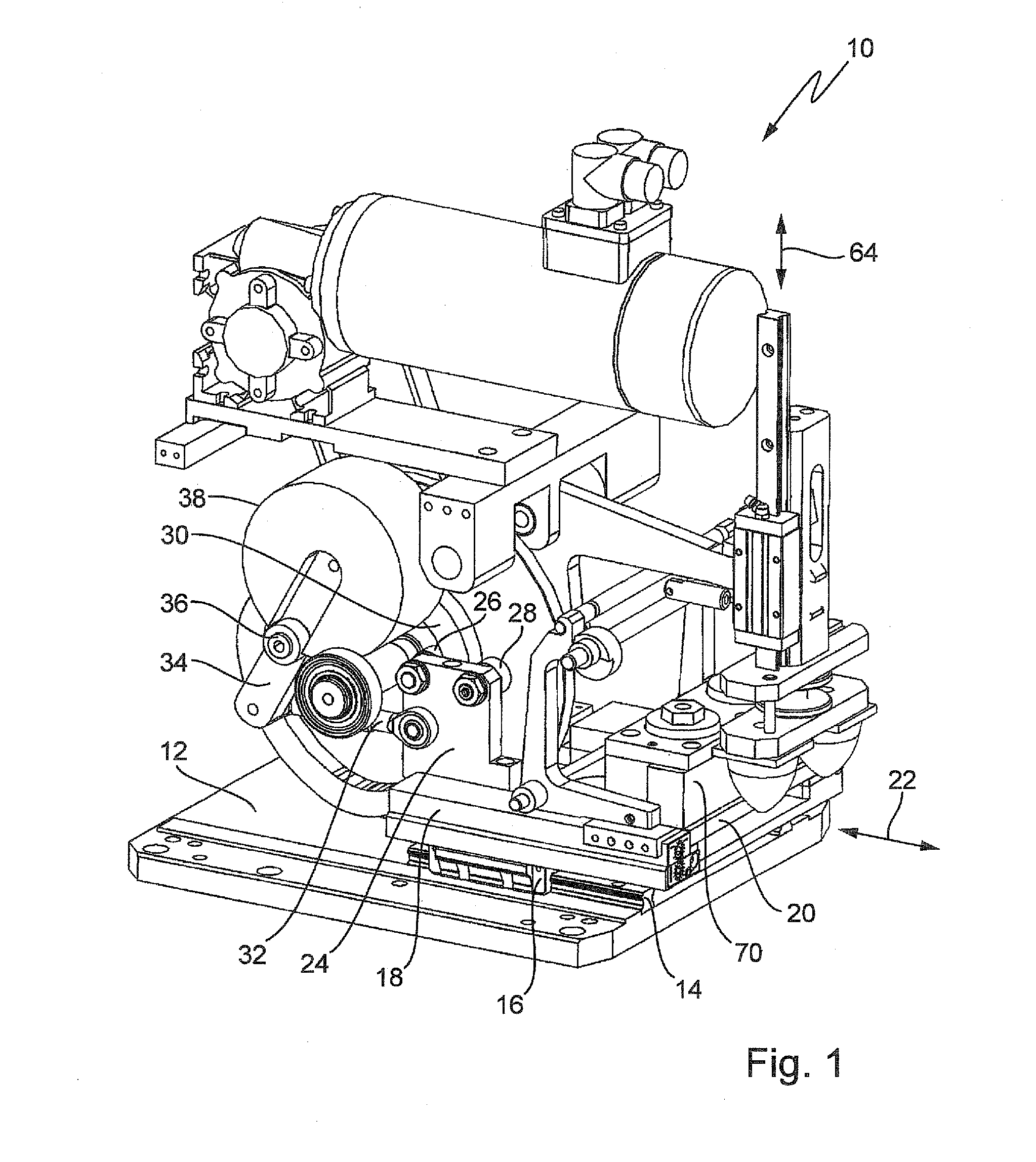
[0009]In one embodiment, the holder may have two support rolls which engage with the first cam, allowing the printing plate to be moved to an inking position and to an ink withdrawal position, and a pivotally supported lever with two support rolls in engagement with the second cam, allowing the lever to be pivoted by the second cam in both pivoting directions, wherein the pad is coupled with the lever. Accordingly, in the pad printing machine according to the invention, the holder for the printing plate is directly provided with the support rolls, so that the holder can be driven directly by the first cam, thereby eliminating possible positional inaccuracies caused by play.
[0011]In one exemplary embodiment of the invention, one of the two support rolls may be springily and / or adjustably attached on the holder and / or on the pivotally supported lever. In this way, the production-related play between the support rolls and the cam is compensated. In addition, installation of the support rolls on the cam is simplified.
[0012]Advantageously, the springily and / or adjustably supported support rolls may contact the first or the second cam with a pretension. In particular, one of the support rolls may be supported so as to be adjustable towards the cam. In this way, for example, the pretension can be generated and adjusted.
[0013]According to another advantageous exemplary embodiment of the invention, the second cam for the ink withdrawal position and optionally for the inking position may have a region shaped as a circular arc or a circle. Optimal printing results are obtained when the printing plate is completely at rest during ink withdrawal, i.e., during the time of the pad contacts the printing plate. This is attained by designing the cam as a circular arc, thereby eliminating (displacement) forces acting on the support roll(s). This can also be advantageous for the inking position, resulting in optimal inking of the engraving. The printing plate experiences maximum acceleration and deceleration between these positions.
[0015]Advantageously, the region for the ink withdrawal position shaped as a circular arc or a circle may extend over an angular range of 40° to 165°, in particular 70° to 155°, and preferably 145°. The pad can then be placed on the printing plate and lifted from the printing plate relatively slowly, thereby preventing or at least significantly reducing resonance oscillations of the pad.
[0016]To ensure that the pad is placed exactly on the printing plate, the pad is supported on a vertical linear guide. This prevents pivoting or displacement of the pad.

Problems solved by technology

In one conventional pad printing machine, the printing plate and the pad are driven by two separate levers operating on control discs, which generates play resulting in inaccurate prints.
Both these pad printing machines have only a limited printing speed.

Method used


Image

  • Pad printing machine
  • Pad printing machine
  • Pad printing machine

Examples


Embodiment Construction

[0027]Throughout all the figures, same or corresponding elements may generally be indicated by same reference numerals. These depicted embodiments are to be understood as illustrative of the invention and not as limiting in any way. It should also be understood that the figures are not necessarily to scale and that the embodiments are sometimes illustrated by graphic symbols, phantom lines, diagrammatic representations and fragmentary views. In certain instances, details which are not necessary for an understanding of the present invention or which render other details difficult to perceive may have been omitted.

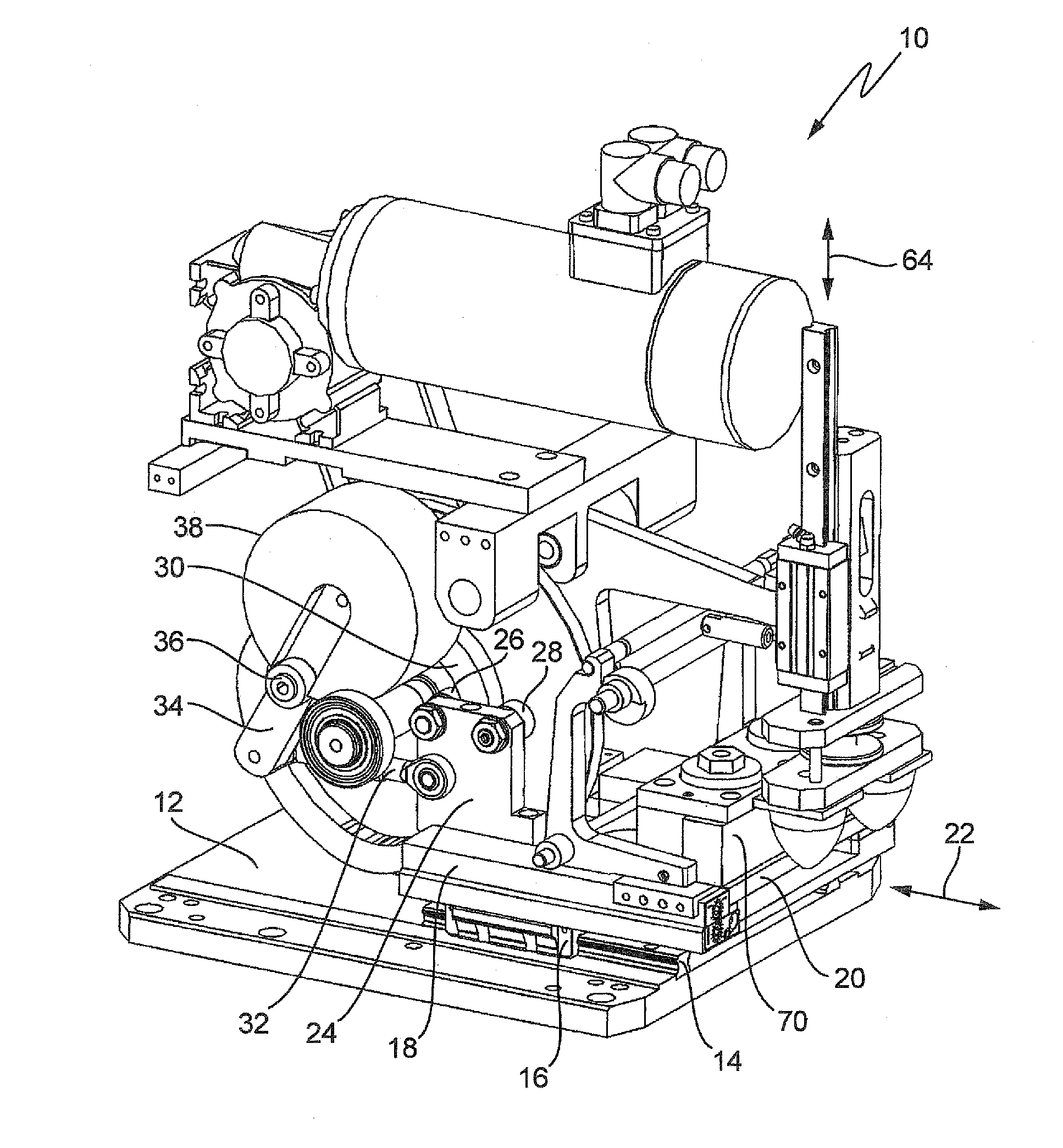
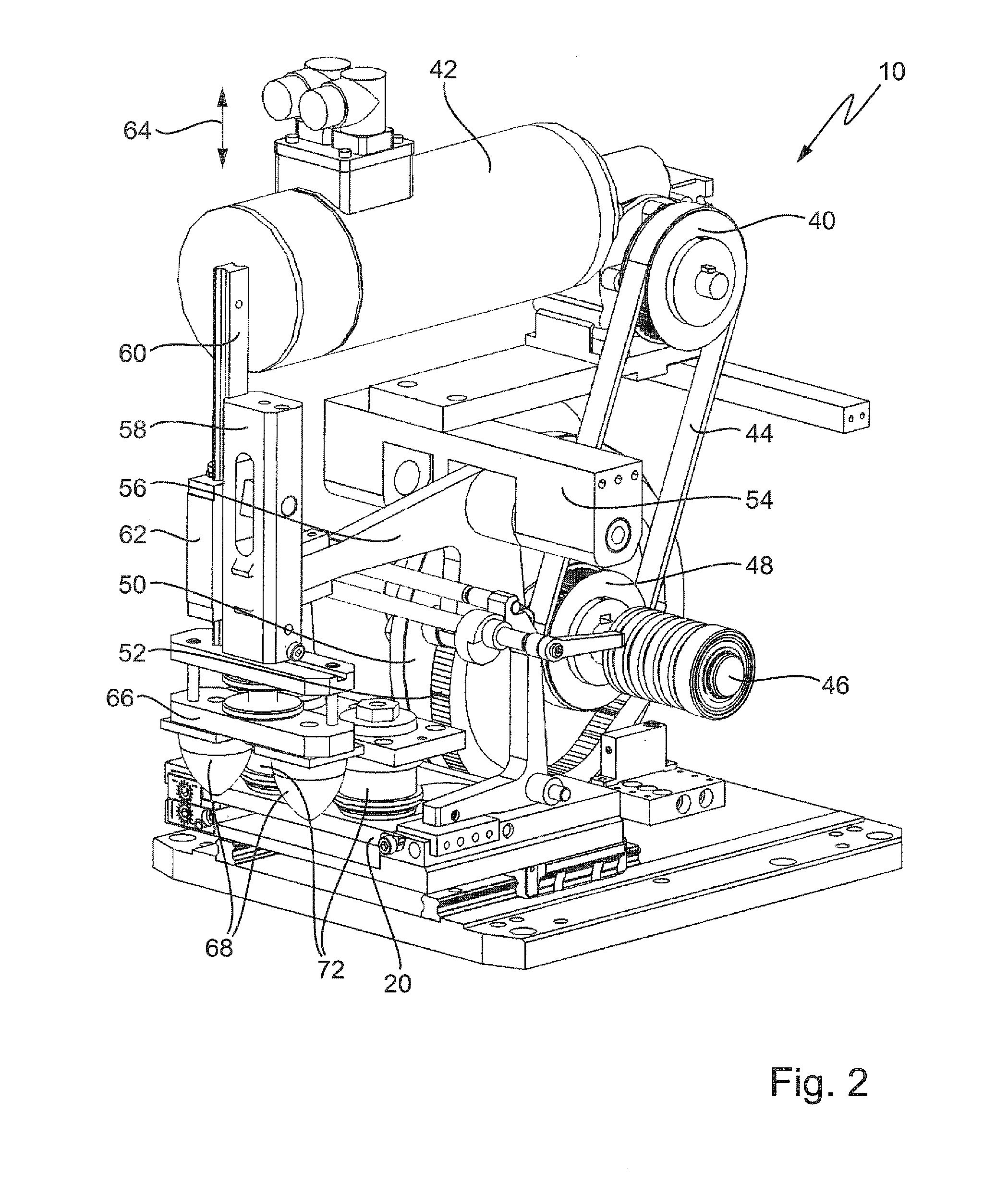
[0028]Turning now to the drawing, and in particular to FIG. 1, there is shown an exemplary embodiment of a pad printing machine 10, wherein only those components relevant for the invention are illustrated. Rails 14 for a carriage 16 are attached to a base plate 12, with a holder 18 for a printing plate 20 being mounted on the carriage 16. The holder 18 with the printing plat...


PUM


Abstract

A pad printing machine with a holder for a printing plate includes an ink supply device having a hollow body which rests with its front face on the printing plate during operation of the machine, a device for producing a relative movement between the printing plate and the hollow body, and a printing pad which can be pressed onto the inked printing plate and receives the ink from recesses in the printing plate and transfers the ink to an object to be printed. The drive assembly for the relative movement between the hollow body and the printing plate has a rotatably driven first cam and the drive assembly for the pad has a rotatably driven second cam, wherein both cams are arranged on a single control disc.

Description

CROSS-REFERENCES TO RELATED APPLICATIONS[0001]This application claims the priority of German Patent Application, Serial No. 10 2010 041 522.7, filed Sep. 28, 2010, pursuant to 35 U.S.C. 119(a)-(d), the content of which is incorporated herein by reference in its entirety as if fully set forth herein.BACKGROUND OF THE INVENTION[0002]The present invention relates to a pad printing machine with a holder for a printing plate, an ink supply device having a hollow body, wherein the hollow body rests with its front face on the printing plate during operation of the machine, a device for generating and relative movement between the printing plate and the hollow body, and a pad which can be pressed onto the inked printing plate and which takes up the ink from the recesses of the printing plate and transfers the ink to an object to be printed, wherein the drive assembly for the relative movement between the hollow body and the printing plate has a rotatably driven first cam and the drive assem...

Claims


Application Information

Patent Timeline
Patent Type & Authority Applications(United States)
IPC IPC(8): B41F1/00
CPCB41F17/001
Inventor NITSCHKE, OLIVERPHILIPP, WILFRIED
Owner TAMPOPRINT
Learn More