Suspension device for a work vehicle

a suspension device and work technology, applied in applications, agricultural machines, transportation and packaging, etc., can solve problems such as uncomfortable riding during non-operational traveling, and achieve the effects of stable digging operation, marked improvement of ride quality, and stable driving power

Inactive Publication Date: 2012-03-29
KOMATSU LTD
View PDF14 Cites 24 Cited by
  • Summary
  • Abstract
  • Description
  • Claims
  • Application Information

AI Technical Summary

Benefits of technology

[0020]According to the invention, the equalizer bar can be locked by the maximum pitch angle changing means so that in cases where either one of the undercarriages rides over an obstacle, the fore parts of both undercarriages with respect to a traveling direction alternately drop onto the ground after simultaneously lifted up from the ground and then the rear parts of both undercarriages with respect to the traveling direction are allowed to land on the ground. More specifically, during nonoperational traveling, the equalizer bar is locked by operating the maximum pitch angle changing means whereby the impact of a drop occurring when either one of the undercarriages rides over an obstacle is not received at one time but received in a plurality of occasions. As a result, the invention can provide ride quality markedly improved over the conventional device during nonoperational traveling.
[0021]In addition, according to the invention, the maximum pitch angle of the equalizer bar is set to a specified angle θ (>0°) during operational traveling such as when digging operation is performed on uneven terrain. The setting of the maximum pitch angle of the equalizer bar to the specified angle θ has the following advantage: Even if either one of the undercarriages is lifted up from the ground on occasions when the undercarriage runs onto an obstacle, the other undercarriage can be kept in contact with the ground in a good condition owing to the balance function of the equalizer bar. Therefore, stable driving power can be ensured even when the vehicle climbs over an obstacle during digging operation on uneven terrain so that stable digging operation on uneven terrain becomes possible.

Problems solved by technology

However, the above-described conventional suspension device has revealed the following problem.
This causes significant impact shock at the time of the drop of the undercarriage, which results in an uncomfortable ride during nonoperational traveling.

Method used


Image

  • Suspension device for a work vehicle
  • Suspension device for a work vehicle
  • Suspension device for a work vehicle

Examples


Embodiment Construction

[0034]Referring now to the accompanying drawings, a suspending device for a work vehicle will be described according to a preferred embodiment of the invention. Although the following embodiment is associated with a case where the invention is applied to a bulldozer that serves as a work vehicle, it is apparent that the invention is not limited to this. When the terms “front-back direction” and “lateral direction” are used herein, it should be understood that these terms are coincident with the front-back and lateral directions as they would appear to the operator sitting on the operator's seat unless otherwise noted.

(Description of Overall Structure of Bulldozer)

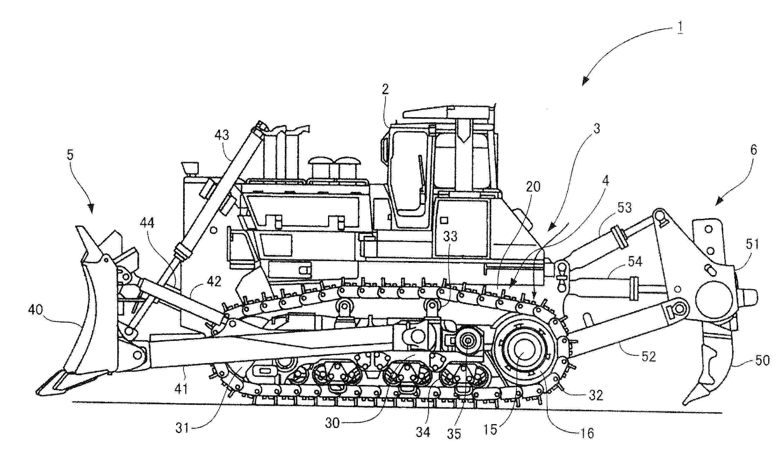
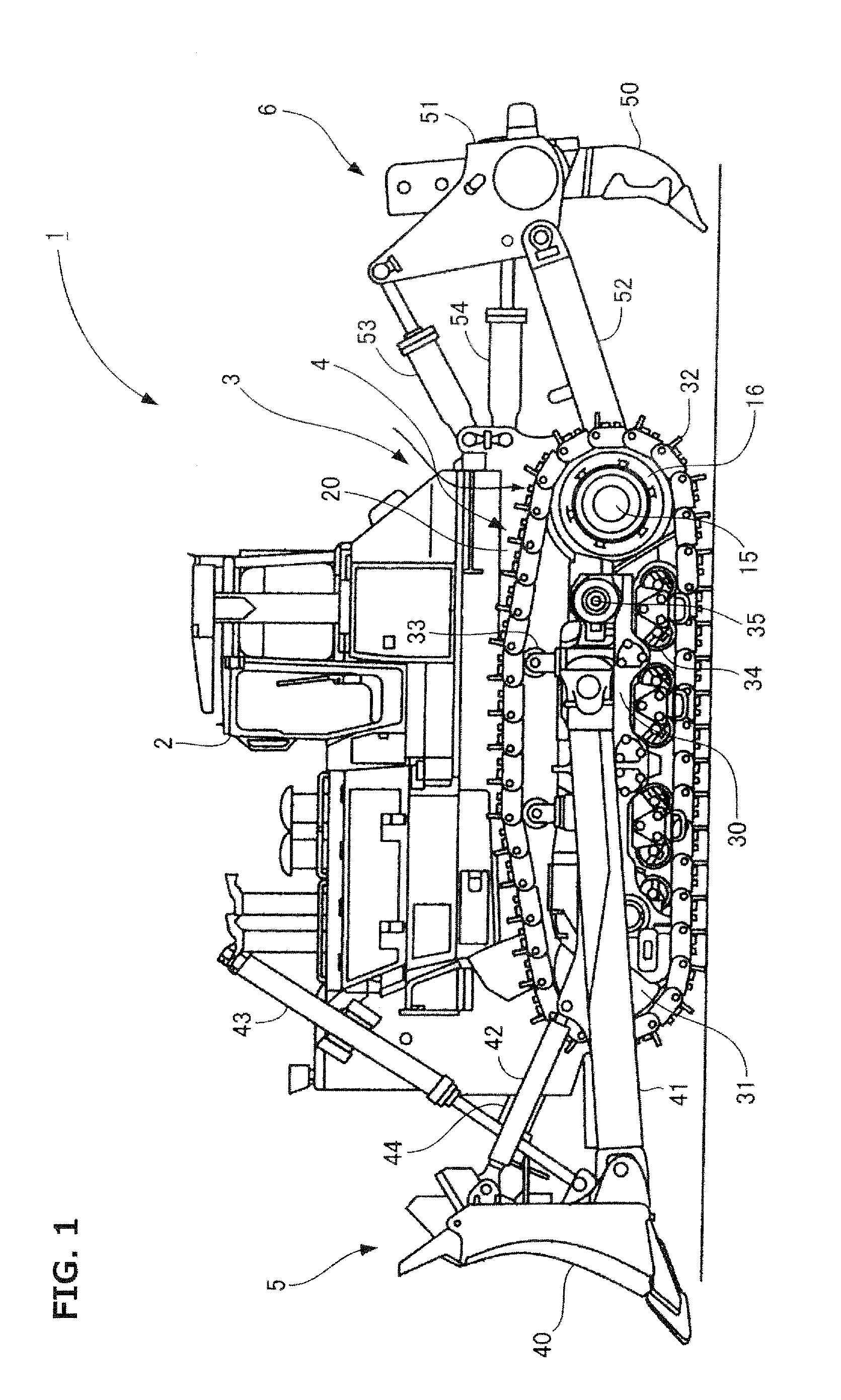
[0035]FIG. 1 shows a bulldozer 1 composed of a vehicle body 3 having a cab 2 that constitutes an operator's cab; track-type undercarriages 4, 4′ provided on the left and right sides of the vehicle body 3 (only the left undercarriage is shown); a front work implement (blade implement) 5 disposed in front of the vehicle body ...


PUM


Abstract

A suspension device for a work vehicle is capable of not only providing improved ride quality during nonoperational traveling such as on-site movement over uneven terrain, but also ensuring stable driving power during operational traveling such as an excavation operation on uneven terrain. The suspension device 60 has an equalizer bar 61 for coupling undercarriages 4, 4′ provided on both sides, respectively, of a vehicle body 3, the equalizer bar 61 being provided in the vehicle body 3 so as to be freely swingable up and down. This suspension device 60 has pitch angle change cylinders 65 as maximum pitch angle changing mechanism for changing the maximum pitch angle of the equalizer bar 61.

Description

TECHNICAL FIELD[0001]The present invention relates to a suspension device for a work vehicle, equipped with an equalizer bar.BACKGROUND ART[0002]A work vehicle such as a bulldozer is composed of a vehicle body and track-type undercarriages mounted to the right and left sides of the vehicle body. Reference is made to the schematic diagrams of FIGS. 9(a) to 9(d) to hereinafter describe a conventional suspension device which is incorporated into a bulldozer such as described above and has an equalizer bar used for providing stable driving power while the bulldozer is operating on uneven terrain.[0003]In the suspension device shown in FIG. 9(a), the front parts of the left and right undercarriages 4, 4′ are coupled to each other by an equalizer bar 61. The central part of the equalizer bar 61 is coupled to the vehicle body (not shown) by a pin having a horizontally extending pivotal axis such that the equalizer bar 61 is freely swingable about the pin, supporting the vehicle body.[0004]...

Claims


Application Information

Patent Timeline
Patent Type & Authority Applications(United States)
IPC IPC(8): A01B63/10A01B63/00
CPCB62D55/084B62D55/0842E02F9/2257E02F9/028B62D55/112
Inventor KURE, KAZUKI
Owner KOMATSU LTD
Why Eureka
Try Eureka