Lead frame structure, a packaging structure and a lighting unit thereof

a packaging structure and lead frame technology, applied in the direction of semiconductor devices, electrical equipment, semiconductor/solid-state device details, etc., can solve the problems of poor reliability and stability of traditional lighting products, two kinds of materials, and plastic housings and lead frames. , to achieve the effect of improving reliability and stability of products, reducing moisture attacks, and increasing combination strength

Active Publication Date: 2012-03-29
LITE ON ELECTRONICS (GUANGZHOU) LTD +1
View PDF7 Cites 100 Cited by
  • Summary
  • Abstract
  • Description
  • Claims
  • Application Information

AI Technical Summary

Benefits of technology

[0006]The objective of the present invention is to provide a lead frame structure, a packaging structure and a lighting unit, which can reduce the moisture attack. The lead frame structure can further used to increase the combination strength between the lead frame and the housing. Thus, the reliability and the stability of product are improved.
[0007]Another objective of the present invention is to provide a lead frame structure, a packaging structure and a lighting unit, in characterized that one of the lead frame structure has an identification structure so that the lead frame units of the lead frame structure, the packaging structure and the lighting unit have a difference in appearance for improve the manufacturing efficiency. Furthermore, the mistakes of mounting the lighting device on the lead frame unit with wrong polarity can be avoided.
[0008]By the at least two grooves formed on the first connection portion, the moisture attack can be reduced so as to protect the lighting device inside the housing.

Problems solved by technology

However, the two kinds of materials, i.e., the housing is plastic and the lead frames are metallic, have weak strength when assembling thereof.
Therefore, the reliability and the stability of the traditional lighting product are bad.
On the other hand, the traditional lead frames have the identical structure and cannot be identified the polarity of the lead frames in appearance.
However, it is easy to mount the lighting emitting diode chip on the wrong side of the lead frames and the manufacturing yield is low.
Thus, the manufacturing efficiency of the product cannot be improved.

Method used


Image

  • Lead frame structure, a packaging structure and a lighting unit thereof
  • Lead frame structure, a packaging structure and a lighting unit thereof
  • Lead frame structure, a packaging structure and a lighting unit thereof

Examples


first embodiment

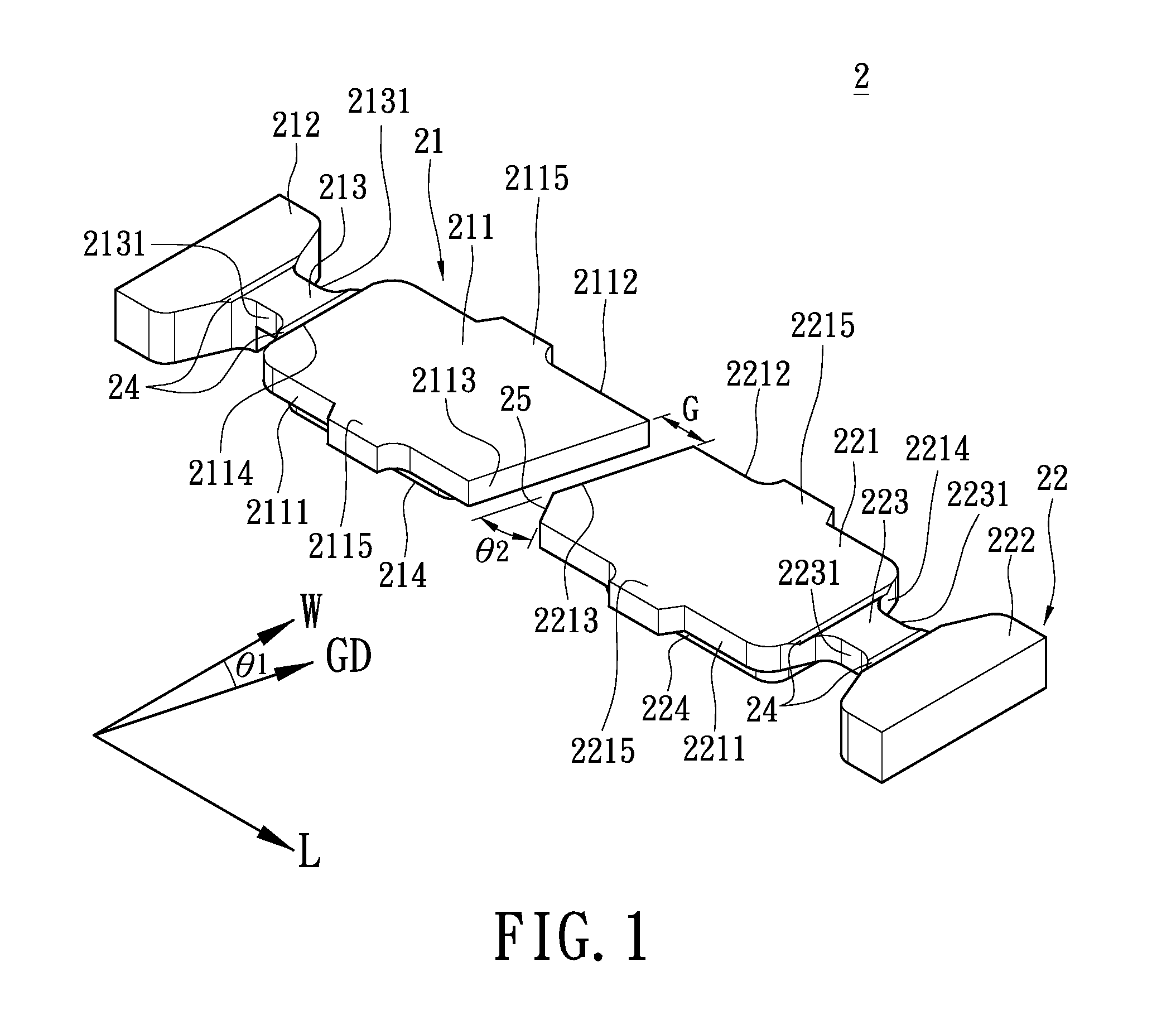
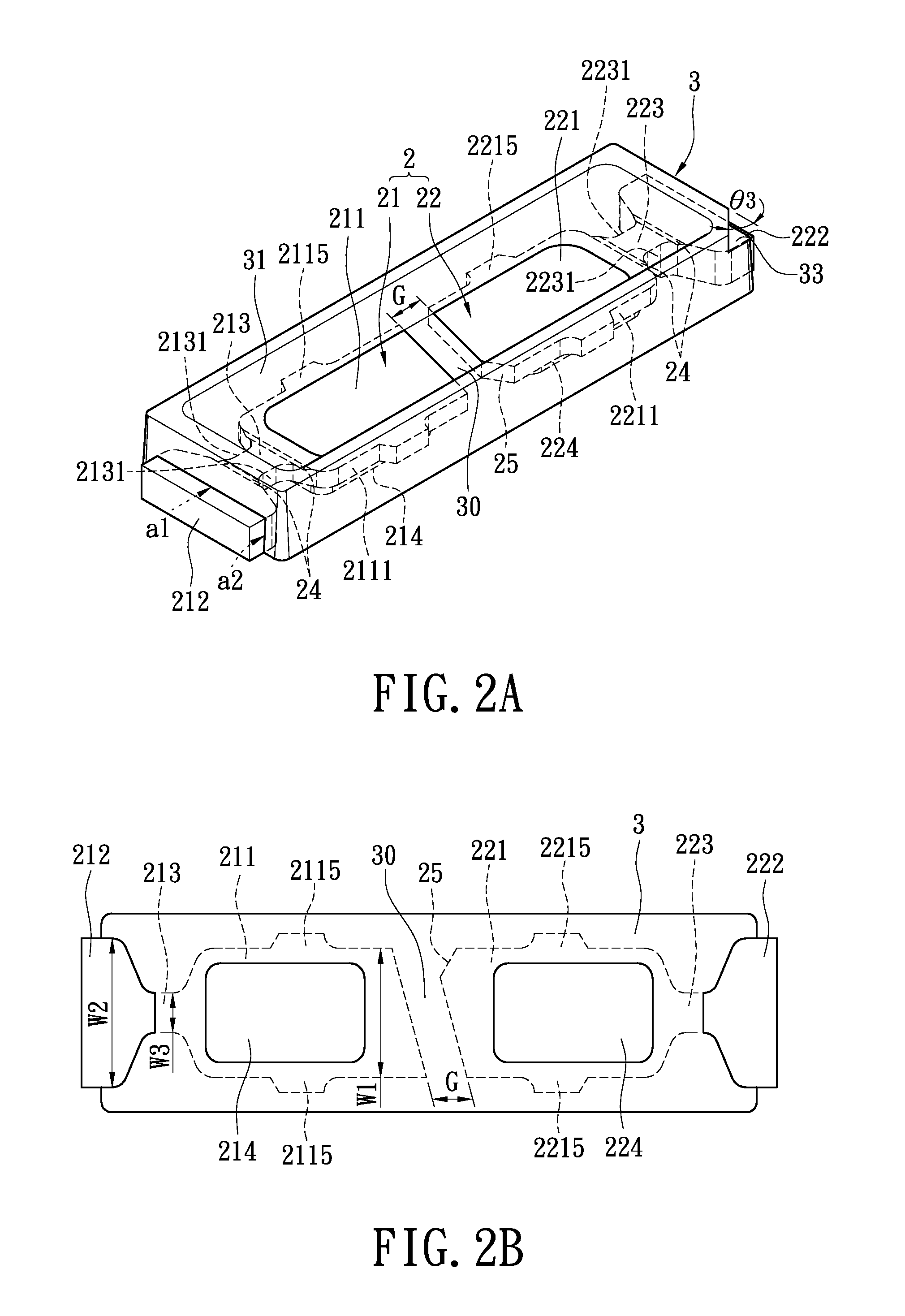
[0020]Please refer to FIG. 1, in which the top-view structural diagram of the lead frame structure 2 of the first embodiment is shown. The lead frame structure 2 has two first lead frame units 21, 22 and there is a gap G between the two first lead frame units 21, 22. The two first lead frame units 21, 22 are arranged in an opposite manner, i.e., the arranging direction of the two first lead frame units 21, 22 are opposite. The first lead frame unit 21 has a first conducting portion 211, a second conducting portion 212, and a first connection portion 213 between the first and the second conducting portions 211, 212. Similarly, the first lead frame unit 22 has a first conducting portion 221, a second conducting portion 222, and a first connection portion 223 between the first and the second conducting portions 221, 222. Moreover, the first connection portion 213 (223) has at least two grooves 24 on a surface thereof. In the exemplary embodiment, the first lead frame unit 21 (22) has t...

third embodiment

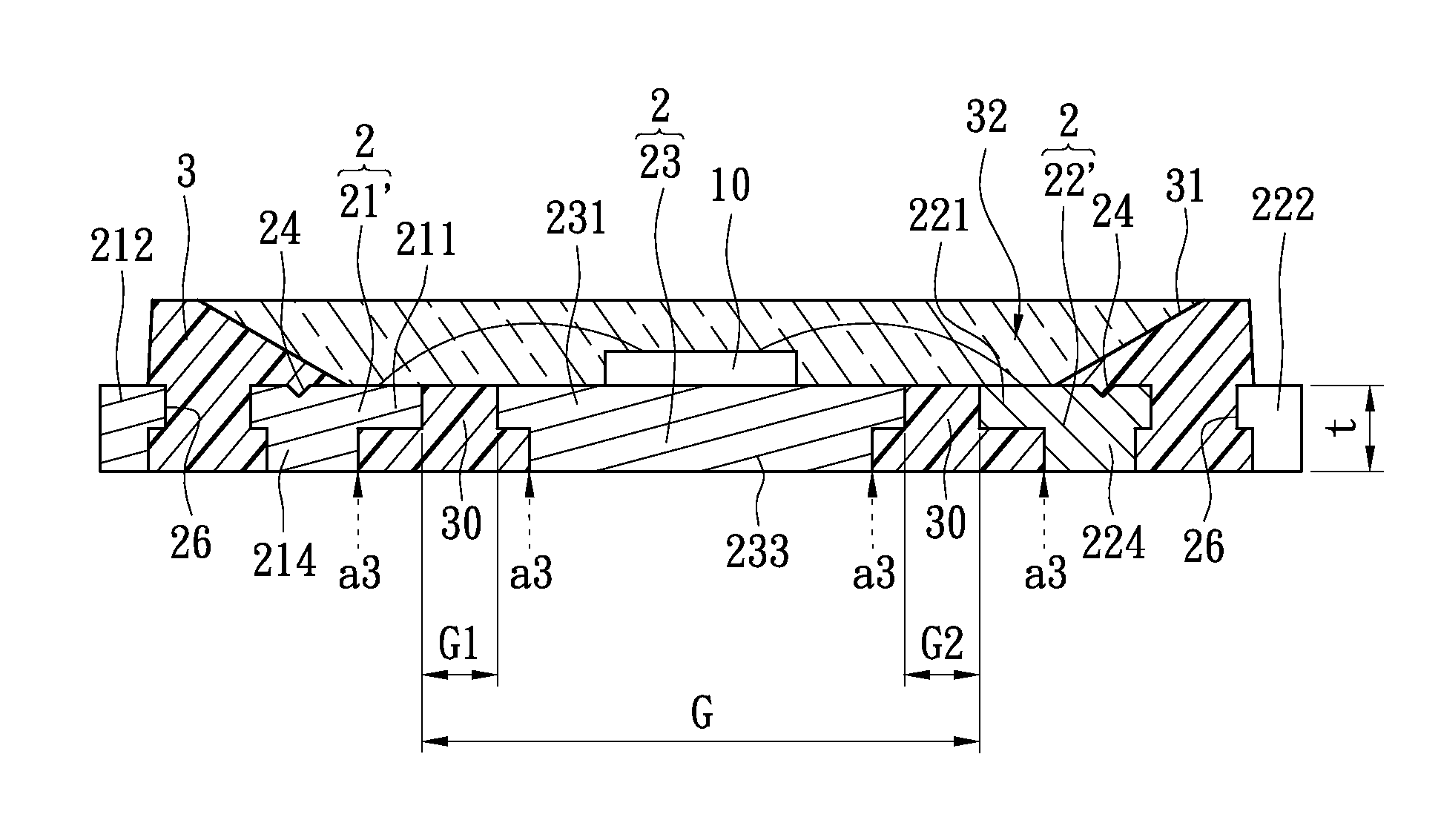
[0051]As shown in FIGS. 6 and 7, the second and that the above-mentioned “N” equals to 2(two) are represented. The housing 3 has two divisions 30, and the lead frame structure 2 has three lead frame units (e.g., the first lead frame units 21 (21′), 22 (22′) and the second lead frame unit 23 (23′)) which arrange along the first direction L. one of the divisions 30 is formed between the adjacent lead frame units. In the embodiment, the middle lead frame unit (i.e., the second lead frame unit 23) is used for mounting lighting device 10 and dissipating heat.

[0052]On the other hand, the lead frame units provide function of conduction of heat or electricity.

[0053]In addition, an encapsulation member 32 covers the lighting device 10. Specifically, the encapsulation member 32 is filled into the concave portion 31 to cover the lighting device 10 and the exposed area of the lead frame units, such as connection portions 211, 221 and the conducting body 231. Preferably, the inner surface of the...


PUM


Abstract

A lead frame structure, a packaging structure and a lighting unit are disclosed. The lead frame structure includes at least two first lead frame units having a space therebetween, and the two first lead frame units are arranged in an opposite manner. Each the first lead frame unit has a first conducting portion, a second conducting portion, and a first connection portion between the first and the second conducting portions. Moreover, the first connection portion has at least two grooves on a surface thereof.

Description

BACKGROUND OF THE INVENTION[0001]1. Field of the Invention[0002]The present invention is a lead frame structure, a packaging structure and a lighting unit having an identification structure; especially, the present invention relates to a lead frame structure, a packaging structure and a lighting unit having a difference in appearance and reducing the moisture attack.[0003]2. Description of Related Art[0004]The traditional lighting emitting diode package is formed by packaging the housing and the lead frames. However, the two kinds of materials, i.e., the housing is plastic and the lead frames are metallic, have weak strength when assembling thereof. As a result, the housing may be easily peeled off from the lead frames, or there may be a space formed between the housing and any one of the lead frames. Environment moisture can enter into the housing through the space to “attack” the circuit of the lighting emitting diode chip and the lead frames inside the housing. Therefore, the rel...

Claims


Application Information

Patent Timeline
Patent Type & Authority Applications(United States)
IPC IPC(8): H01L33/52H01L23/495
CPCH01L33/62H01L33/642H01L2224/48091H01L2224/48247H01L2933/0066H01L2924/00014
Inventor LIN, CHEN-HSIU
Owner LITE ON ELECTRONICS (GUANGZHOU) LTD
Why Eureka
Try Eureka