Optical Scope

a technology of optical scope and optical lens, which is applied in the field of optical scope, can solve the problems of difficult to manufacture the prism, complicated procedures and time, and the aimed shooting method requires complicated procedures and time, and achieve the effects of reducing damage, increasing eye relief, and quickly acquiring the motion of the target and its surroundings

Active Publication Date: 2012-03-29
JUNG IN
View PDF8 Cites 19 Cited by
  • Summary
  • Abstract
  • Description
  • Claims
  • Application Information

AI Technical Summary

Benefits of technology

[0019]Accordingly, the present invention is conceived to solve the forgoing problems, and an aspect of the present invention is to provide an optical scope in which a lens having negative power is disposed on an image formation surface of an

Problems solved by technology

That is, an aimed-shooting method requires complicated procedures and time to acquire and ascertain a target, arrange the line of sight, a

Method used


Image

  • Optical Scope
  • Optical Scope
  • Optical Scope

Examples


Embodiment Construction

[0047]Prior to description, elements will be representatively explained in an embodiment and only different configurations will be described in another embodiment, in which like reference numerals refer to like elements throughout the embodiments.

[0048]Hereinafter, an optical scope according to a first exemplary embodiment of the present invention will be described with reference to the accompanying drawings.

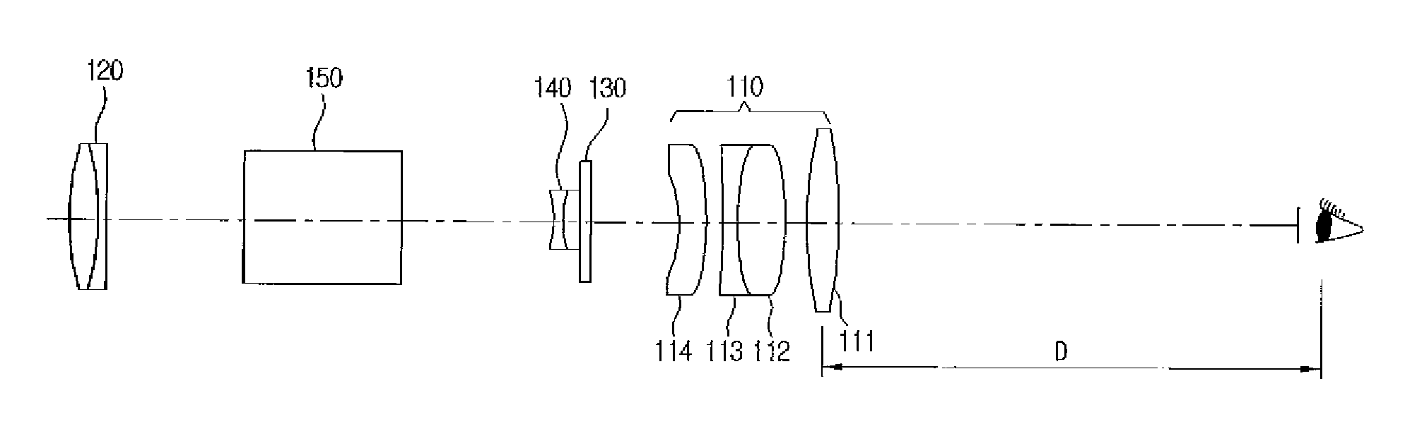
[0049]Among the accompanying drawings, FIG. 6 is a cross-section view of an optical scope according to an exemplary embodiment of the present invention.

[0050]As shown therein, the optical scope in this exemplary embodiment includes an eyepiece lens 110, an objective lens 120, a reticle 130, a field lens 140 having negative power, and an erecting optical system 150.

[0051]In this exemplary embodiment, the field lens 140 having negative power is disposed between the eyepiece lens 110 and the objective lens 120, so that a space between the eyepiece lens 110 and a user's eyes, i.e., ...


PUM


Abstract

Disclosed is an optical scope including an objective lens, an eyepiece lens, and a reticle, wherein a field lens having negative power is disposed in at least one of a front and a back of the reticle disposed on an image formation surface of the objective lens to increase eye-relief.

Description

CROSS-REFERENCE TO RELATED APPLICATION[0001]This application claims priority to and the benefit of Korean Patent Application No. 10-2010-0094809 filed in the Korean Intellectual Property Office on Sep. 29, 2010, the entire contents of which are incorporated herein by reference.BACKGROUND OF THE INVENTION[0002](a) Field of the Invention[0003]The present invention relates to an optical scope, and more particularly, to an optical scope in which a lens having negative power is disposed on an image formation surface of an objective lens, thereby increasing eye-relief.[0004](b) Description of the Related Art[0005]In firearms, a sighting means may be coupled to a top portion of the firearm so as to accurately aim an external target. In a particular case of a rifle among the firearms, aiming is achieved by aligning a line of sight between a sight and a bead, in which speed showing how quickly the aiming is achieved to fire an aimed shot and accuracy showing how accurately the aimed shot hit...

Claims


Application Information

Patent Timeline
IPC IPC(8): G02B23/02G02B23/00
CPCF41G1/38G02B23/105G02B17/045G02B23/00G02B23/02G02B25/001G02B27/32
Inventor JUNG, INLEE, DONG HEE
Owner JUNG IN
Why Eureka
Try Eureka