Feeding device

a technology of feeding device and feed line, which is applied in the direction of loading/unloading, thin material processing, furnace, etc., can solve the problems of sinuous conveying line and occupies too much spa

Inactive Publication Date: 2012-03-29
HONG FU JIN PRECISION IND (SHENZHEN) CO LTD +1
View PDF10 Cites 42 Cited by
  • Summary
  • Abstract
  • Description
  • Claims
  • Application Information

AI Technical Summary

Benefits of technology

[0004]During a production process, workpieces are placed in feeding trays, and the feeding trays are transferred between different machining stations by a conveying line. If feeding trays are reused, the conveying line becomes sinuous, which occupies too much space. For workpieces that need to be held in a specific position before conveying to next machining station, the conveying line needs to be elongated, further occupying even more space.

Problems solved by technology

If feeding trays are reused, the conveying line becomes sinuous, which occupies too much space.

Method used


Image

  • Feeding device
  • Feeding device
  • Feeding device

Examples


Embodiment Construction

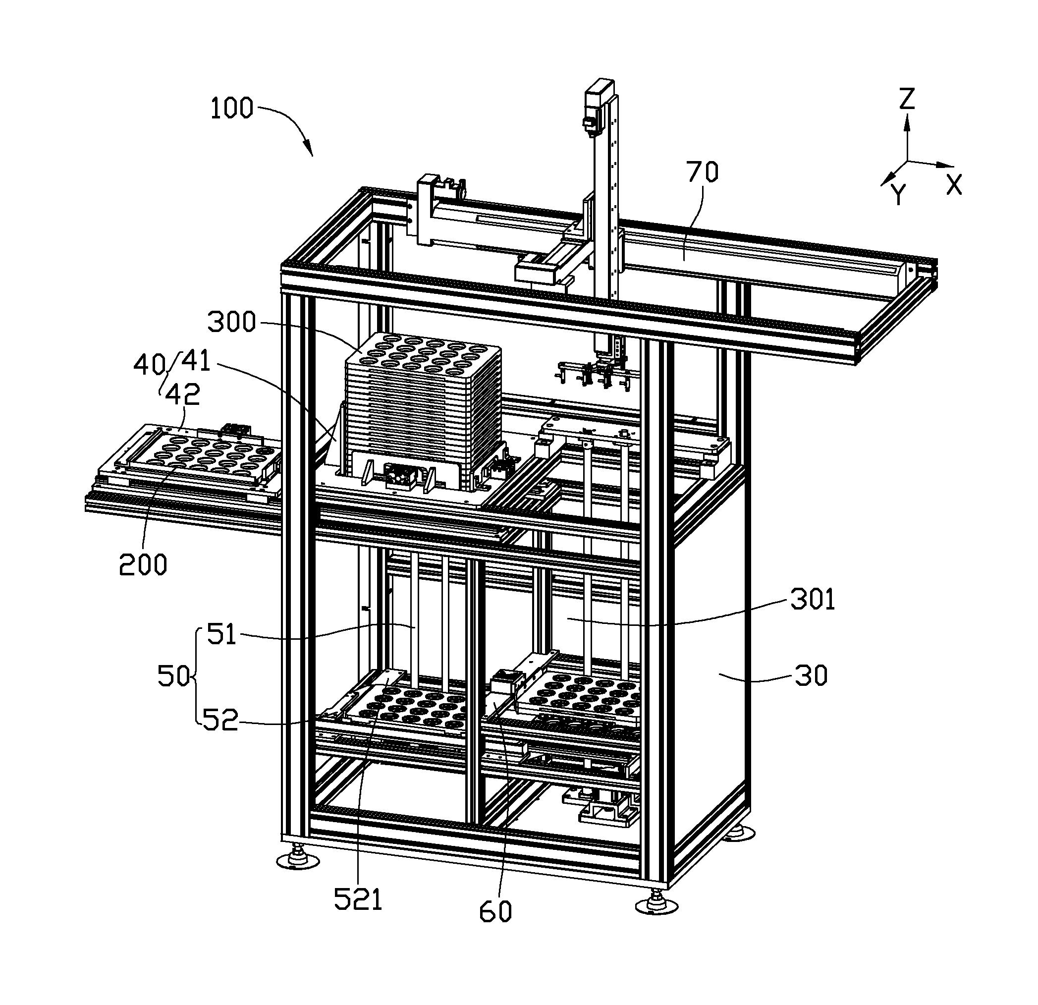
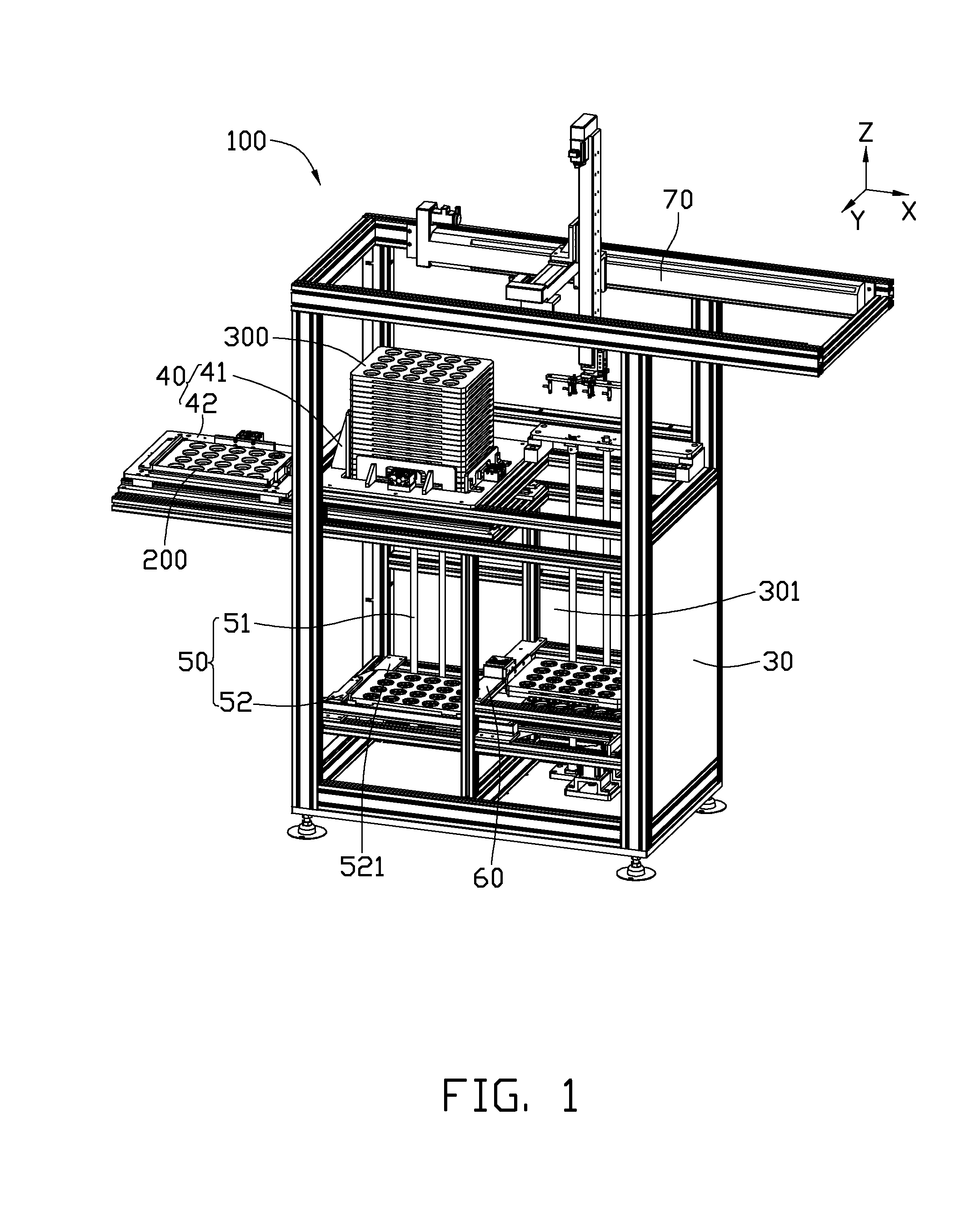
[0015]Referring to FIG. 1, one embodiment of a feeding device 100 is used for transferring feeding trays 300 for receiving workpieces 200 between a first station and a second station. The feeding device 100 includes a fixing frame 30, a first conveying mechanism 40, a second conveying mechanism 50, a stacking mechanism 60, and a handling mechanism 70. In the illustrated embodiment, the workpiece 200 is formed by injection, and then transferred from an injection station to a testing station for testing a size of the workpiece 200. When the workpiece 200 is newly formed, the temperature of the workpiece 200 is relatively high, and the size of the workpiece 200 is affected by the temperature. Therefore, the workpiece 200 needs to be cooled down to room temperature before testing, such that the feeding time between the injection station and the testing station is equal to or longer than the cooling time.

[0016]The fixing frame 30 is substantially rectangular, and defines a receiving spac...


PUM


Abstract

A feeding device transferring feeding trays with workpieces between a first station and a second station includes a fixing frame, a first conveying mechanism, a second conveying mechanism, and a stacking mechanism. The first conveying mechanism is mounted on the fixing frame for conveying feeding trays to the first station one by one. The second conveying mechanism is mounted on the fixing frame for conveying the feeding trays from the first station one by one, and is connected to the first conveying mechanism. The stacking mechanism is mounted on the fixing frame for stacking the feeding trays together.

Description

BACKGROUND[0001]1. Technical Field[0002]The present disclosure relates to feeding devices, and particularly, to a feeding device for transferring feeding trays.[0003]2. Description of the Related Art[0004]During a production process, workpieces are placed in feeding trays, and the feeding trays are transferred between different machining stations by a conveying line. If feeding trays are reused, the conveying line becomes sinuous, which occupies too much space. For workpieces that need to be held in a specific position before conveying to next machining station, the conveying line needs to be elongated, further occupying even more space.[0005]Therefore, there is room for improvement within the art.BRIEF DESCRIPTION OF THE DRAWINGS[0006]The components in the drawings are not necessarily drawn to scale, the emphasis instead being placed upon clearly illustrating the principles of the present disclosure. Moreover, in the drawings, like reference numerals designate corresponding parts t...

Claims


Application Information

Patent Timeline
Patent Type & Authority Applications(United States)
IPC IPC(8): B65G49/00B65G57/00
CPCB65G47/912B65G65/00B65G59/062B65G57/302
Inventor WANG, HUILIU, WEI-HUA
Owner HONG FU JIN PRECISION IND (SHENZHEN) CO LTD
Why Eureka
Try Eureka