

Syringe drive device
a drive device and syringe technology, applied in the direction of packaging foodstuffs, packaged goods types, pharmaceutical containers, etc., can solve the problems of significantly deteriorating workability and 1 was not particularly designed to address syringes, so as to improve workability, improve workability in suctioning medicinal solutions, and facilitate manipulation of a plurality of different syringes
- Summary
- Abstract
- Description
- Claims
- Application Information
AI Technical Summary
Benefits of technology
Problems solved by technology
Method used
Image

Examples
embodiment 1
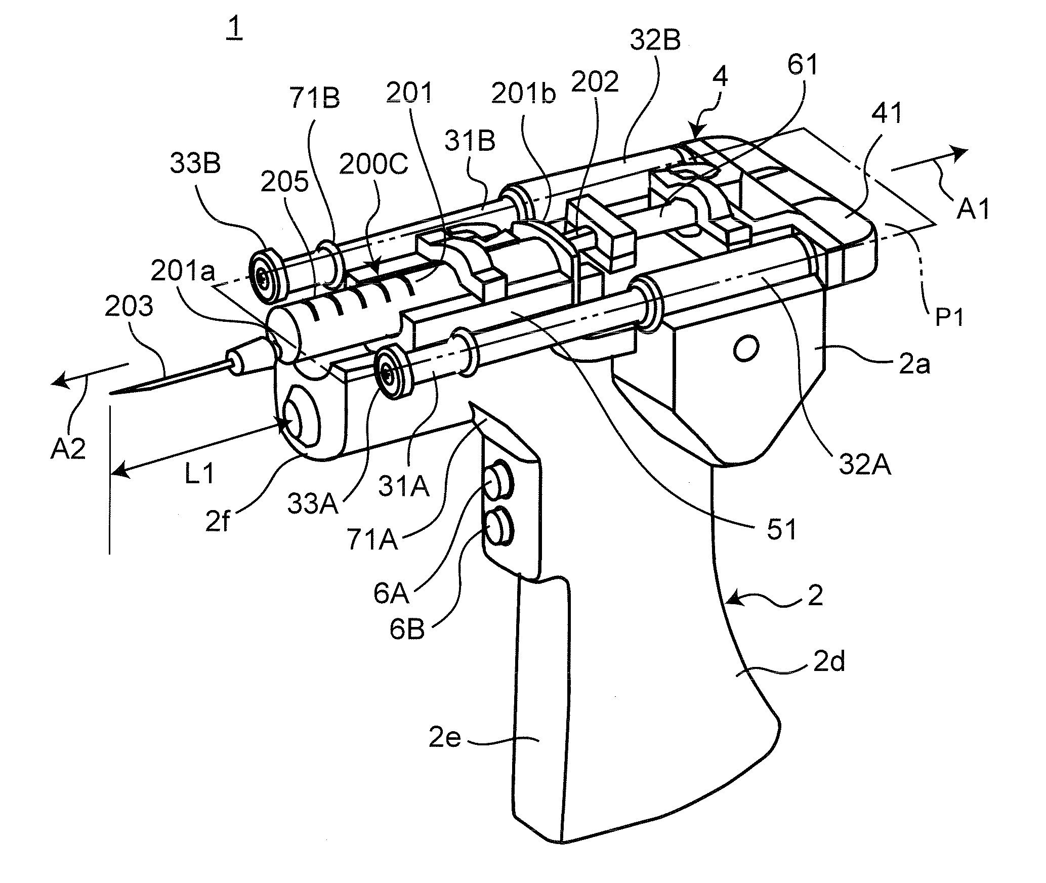
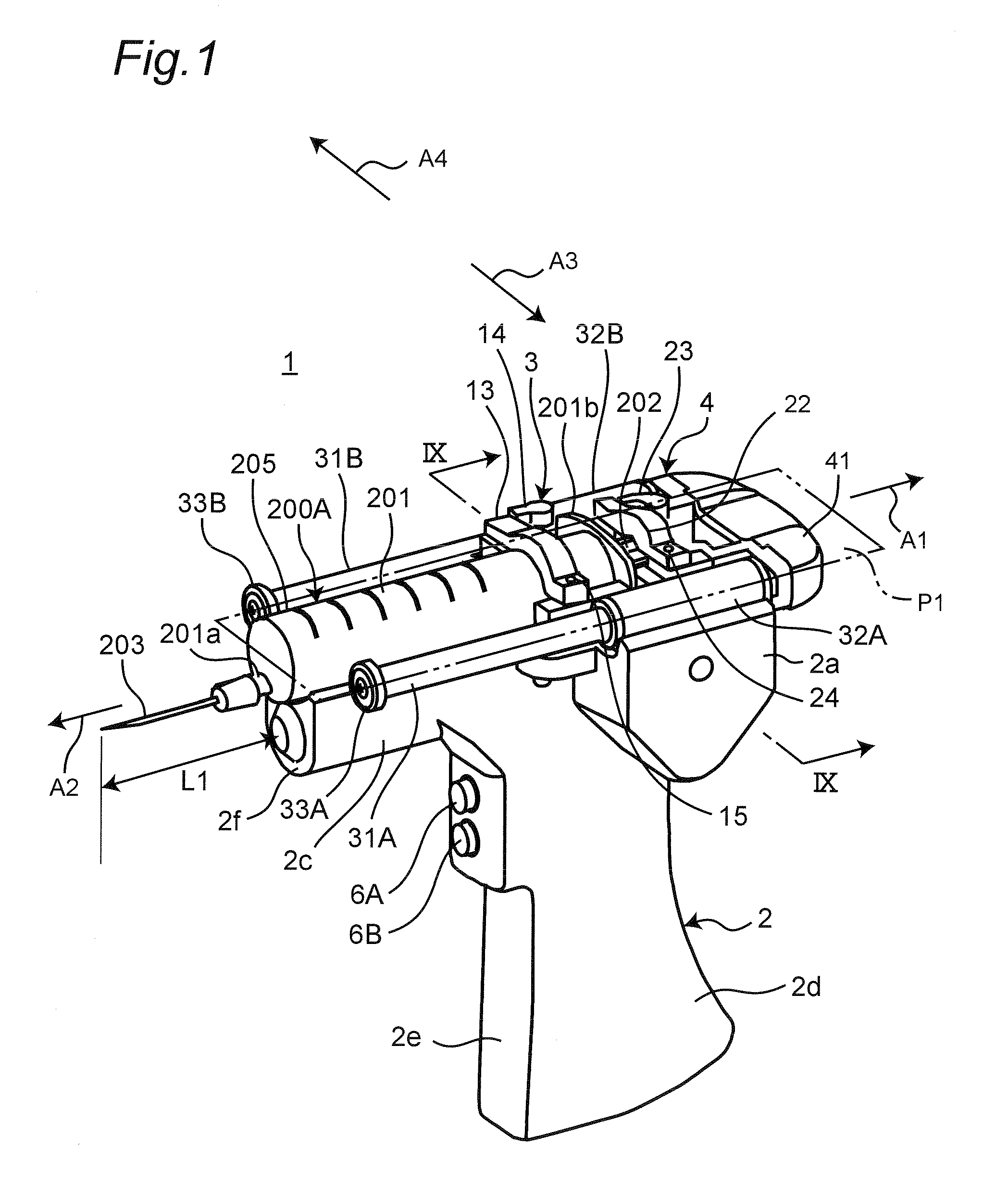
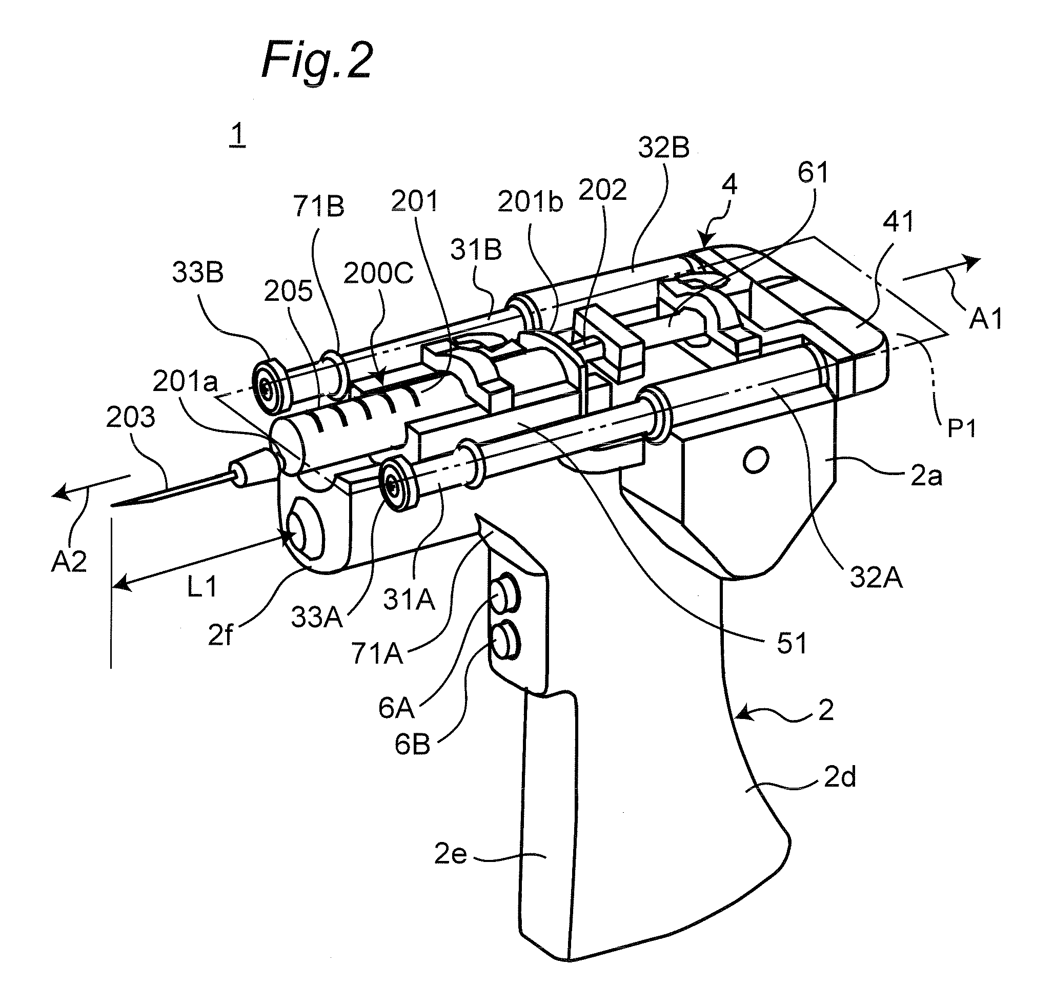
[0030]FIGS. 1 and 2 illustrate a syringe drive device 1 of mobile type according to an embodiment 1 of the present invention. The syringe drive device 1 drives a piston of a syringe used in a medication dispensing operation, such as a mixing operation to prepare an injection solution or a drip-feed solution. The syringe drive device 1 can be loaded with any of a large syringe 200A (FIG. 1) and a small syringe 200C (FIG. 2) in which cylinders 201 respectively have different shapes and jaw portions 202a of pistons 202 at the initial positions are differently located. When the small syringe 200C is loaded in the syringe drive device 1, a cylinder adapter 51 and a piston adapter 61 which are described later are used.
[0031]Hereinafter is described a basic structure of the syringe drive device 1 where neither of the cylinder adapter 51 nor the piston adapter 61 is used (no adapter is used). In the description given below, left side of the syringe drive device 1 on the drawing of FIG. 1 ma...
embodiment 2
[0070]FIGS. 10 to 12 illustrate a syringe drive device 1 according to an embodiment 2 of the present invention. In the syringe drive device 1 according to the present embodiment, any of the large syringe 200A and the intermediate syringe 200B among the syringes illustrated in FIG. 14 with different storage capacities can be loaded and used without replacing any device components. As illustrated in FIG. 11A, a piston adapter 82 alone is used when the large syringe 200A is loaded in the syringe drive device 1. As illustrated in FIG. 11B, a cylinder adapter 81 and the piston adapter 82 are both used when the intermediate syringe 200B is loaded in the syringe drive device 1.
[0071]As illustrated with a reference symbol α1 in FIGS. 12 and 14, there is only a relatively small difference between distances from the flange portions 201b of the respective cylinders 201 to the ends (ends of the respective solution ports 201a) in the large syringe 200A and the intermediate syringe 200B. Therefor...
embodiment 3
[0076]FIG. 13 illustrates a medication dispensing device 91 to which the syringe drive device 1 according to the embodiment 1 is applied.
[0077]A movable section 92 of the medication dispensing device 91 has a syringe drive device holding section 97 which retains a syringe drive device 1 similar to the syringe drive device according to the embodiment 1 on one end side thereof, and a container holding section 93 on the other end side thereof. The container holding section 93 has openable and closable clamps 94A and 94B which detachably retain a medicinal solution container (vial container 300 in the present embodiment). The container holding section 93 linearly reciprocates on the movable section 92 in directions illustrated with arrows B1 and B2. When the container holding section 93 moves in the direction of arrow B1, the vial container 300 moves toward a syringe 200 loaded in the syringe drive device 1. When the container holding section 93 moves in the direction of arrow B2, the v...
PUM
 Abstract
Description
Claims
Application Information