Methods And Apparatus For Preparing An Intercondylar Area Of A Distal Femur

a distal femur and intercondylar area technology, applied in the field of methods and apparatus for preparing the intercondylar area of the distal femur, can solve the problems of high stress concentration, significant possibility of femoral fracture, and concentrated bone stress

Active Publication Date: 2012-03-29
ARTHREX
View PDF1 Cites 5 Cited by
  • Summary
  • Abstract
  • Description
  • Claims
  • Application Information

AI Technical Summary

Problems solved by technology

These sharp corners lead to concentrated bone stresses and the significant possibility of femoral fracture.
In some cases, the corners are overcut, where the saw violates the adjacent resection, leading to a very high stress concentration.
This method also leads to an excessive amount of bone being removed from the intercondylar area.
The more bone that is removed, however, the more likely it is to: (i) compromise the integrity of the modified structures of the femur, and / or (ii) compromise the recovery of the patient.
As mentioned above, however, the intercondylar bone is very hard and can be very difficult to punch.
More problematically, however, is the fact that the punch may result in small or large cracks in the remaining bone of the distal femur.
Such cracks may be apparent at the time of surgery or may represent latent damage.
In either case, the punch technique may lead to high stress concentrations (at sharp corners and / or cracks), excessive bone removal, a compromise of the structural integrity of the modified femur, and / or limited recovery of the patient.
While using a milling device and a notch preparation guide may provide some improvement in the notch preparation, there is a significant disadvantage.
Rather, the milling device creates a “dust” that is relatively useless.

Method used


Image

  • Methods And Apparatus For Preparing An Intercondylar Area Of A Distal Femur
  • Methods And Apparatus For Preparing An Intercondylar Area Of A Distal Femur
  • Methods And Apparatus For Preparing An Intercondylar Area Of A Distal Femur

Examples


Embodiment Construction

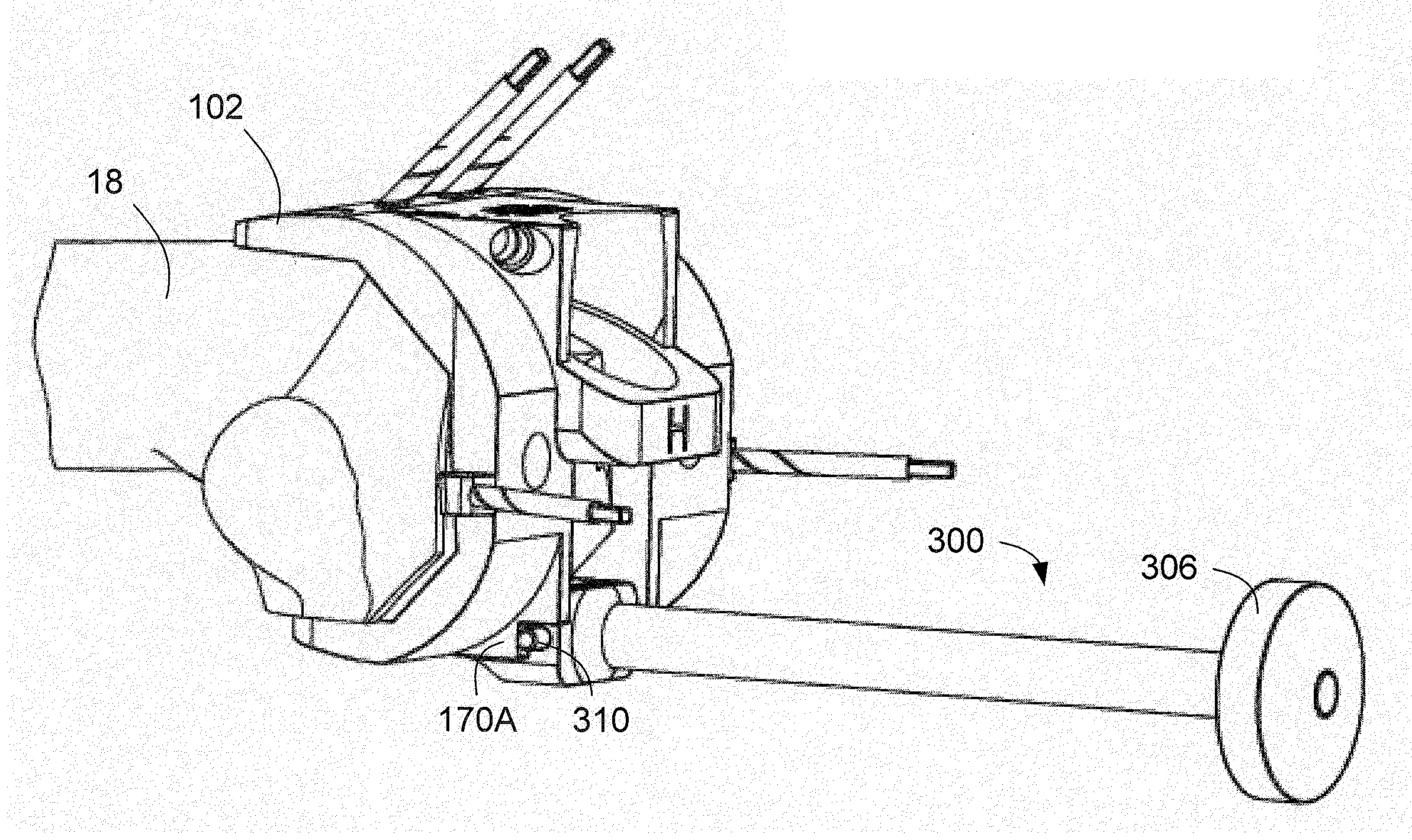
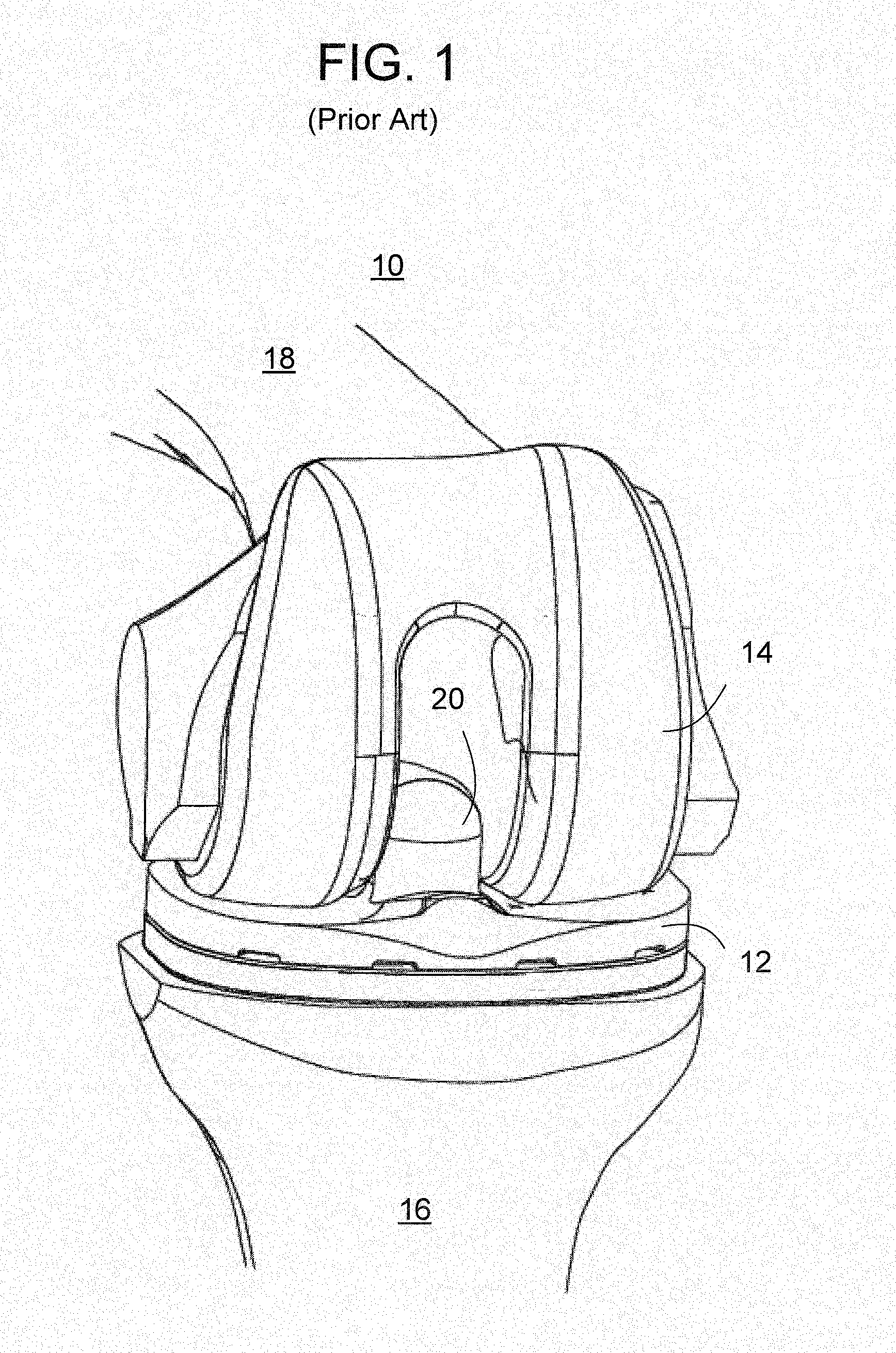
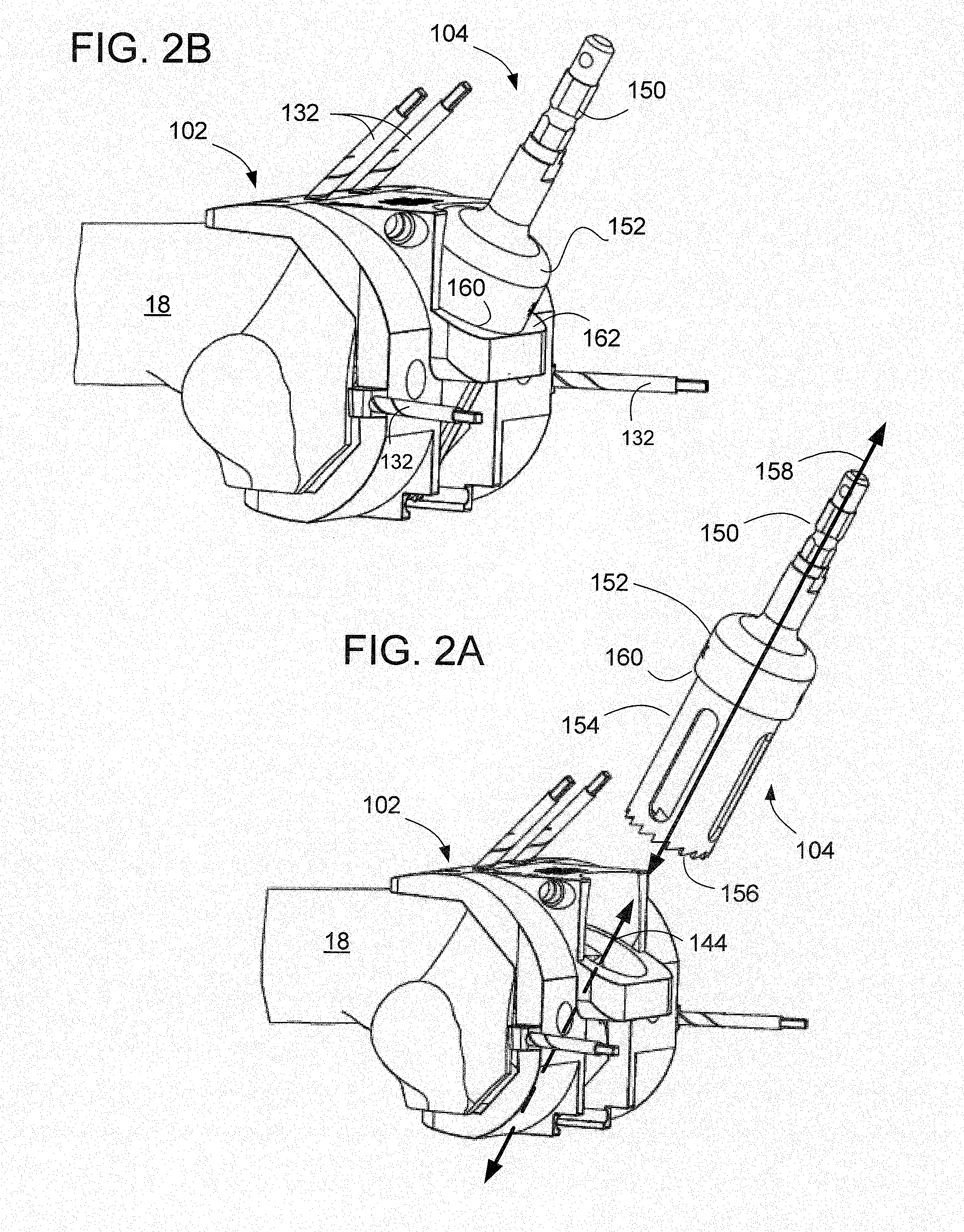
[0029]With reference to the drawings, wherein like numerals indicate like elements, there is shown in FIGS. 2A and 2B a system 100 for modifying the intercondylar notch of a patient's femur 18. The system includes a guide 102 and a hole saw 104. The guide 102 is sized and shaped to firmly engage the distal end of the patient's femur 18 and to provide a well defined orientation of the hole saw 104 such that a cutting edge of the hole saw 104 removes a desired portion of material from the intercondylar notch. As will be discussed in more detail below, the defined orientation and structural characteristics of the hole saw 104, vis-à-vis the guide 102, removes the material from the intercondylar notch of a patient's femur 18 in such a way as to create clearance for certain structural features of a knee prosthesis, such as a posteriorly stabilized prosthetic knee system for total knee replacement. As discussed previously, these structures may include one or more of the cam 21 of the femo...


PUM


Abstract

Methods and apparatus provide for modifying an intercondylar notch of a patient's femur, including cutting bone from the intercondylar notch using a hole saw having a hollow cylinder and a circular cutting edge, where the hollow cylinder of the hole saw defines a central longitudinal axis which is oriented with reference to the patient's femur such that the circular cutting edge of the hole saw removes a portion of material from the intercondylar notch of the patient's femur.

Description

BACKGROUND OF THE INVENTION[0001]The present invention relates to methods and apparatus for modifying an intercondylar area of a patient's femur in order to prepare same for receiving a knee prosthesis.[0002]There are a number of different categories of prosthetic knee systems that are used in total knee replacement surgery. Among these categories is the posteriorly stabilized prosthetic knee system, where the posterior cruciate ligament is either weakened or non-present due to injury or disease, or where the posterior cruciate ligament is sacrificed during the knee replacement procedure itself.[0003]FIG. 1 illustrates a knee that has been repaired using a known posteriorly stabilized prosthetic knee system 10. The system 10 includes a posteriorly stabilized tibial bearing component 12 and a posteriorly stabilized femoral component 14, which are coupled to the patient's tibia 16 and femur 18, respectively. The femoral component 14 is slotted (including a cam 21, not shown) and the t...

Claims


Application Information

Patent Timeline
Patent Type & Authority Applications(United States)
IPC IPC(8): A61B17/56
CPCA61B17/1604A61B17/1635A61B2019/304A61B17/1675A61B17/1764A61B17/1637A61B2090/034
Inventor FEARON, KEVINNAPOLITANO, PATRICKTUNER, JAMESKUCZYNSKI, JOHN
Owner ARTHREX
Why Eureka
Try Eureka