Front wheel energy recovery system

a technology of energy recovery and front wheels, which is applied in the direction of vehicle position/course/altitude control, process and machine control, instruments, etc., can solve the problems of large battery size, increased cost, and insufficient battery technology, so as to avoid creating a torque steering effect, improve vehicle dynamics and safety for the rider, and easily install a hydraulic version

Inactive Publication Date: 2012-04-05
W MORRISON CONSULTING GRP
View PDF76 Cites 61 Cited by
  • Summary
  • Abstract
  • Description
  • Claims
  • Application Information

AI Technical Summary

Benefits of technology

The front wheel KERS system for a motorcycle described in this patent has several technical benefits. Firstly, it provides a mechanical system that balances torque reactions and moments of inertia, which improves the vehicle's dynamics and safety for the rider. Secondly, it can be easily installed on existing motorcycles with minimal modifications. Thirdly, it allows for the transfer of significant energy from the front wheel to an electricity generating device located separately from the front wheel without interfering with the steering range of motion or the telescoping action of the front suspension. Fourthly, it extends the life of the on-board electrical accumulator charge and allows for the use of more powerful motors with smaller battery packs. Fifthly, it allows for comprehensive control over the KERS system through both manual and automatic controls.

Problems solved by technology

The technical problem being solved in this patent text is finding ways to effectively utilize the excess energy captured from the front wheel of a motorcycle, while avoiding interference with the driver's ability to handle and safely control the vehicle. Previous attempts at implementing regenerative braking systems have proven difficult, expensive, unreliable, or unsafe for motorcycling purposes. There is a need for a new system that captures significant energy from the front wheel, is lightweight, efficient, and doesn't negatively affect the vehicle's dynamic response or safety.

Method used


Image

  • Front wheel energy recovery system
  • Front wheel energy recovery system
  • Front wheel energy recovery system

Examples


Embodiment Construction

[0058]Reference will now be made in detail to various embodiments, examples of which are illustrated in the accompanying drawings.

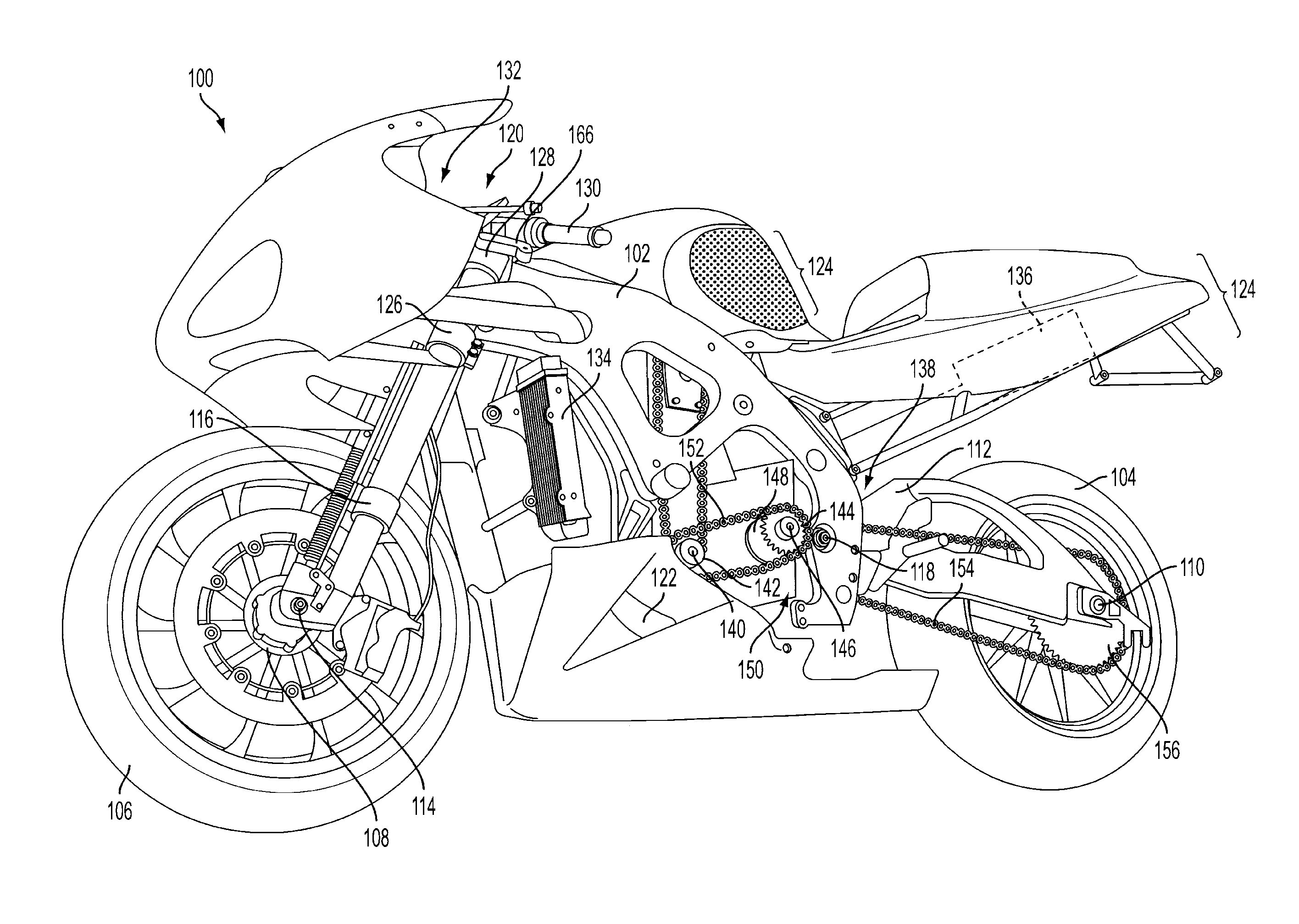
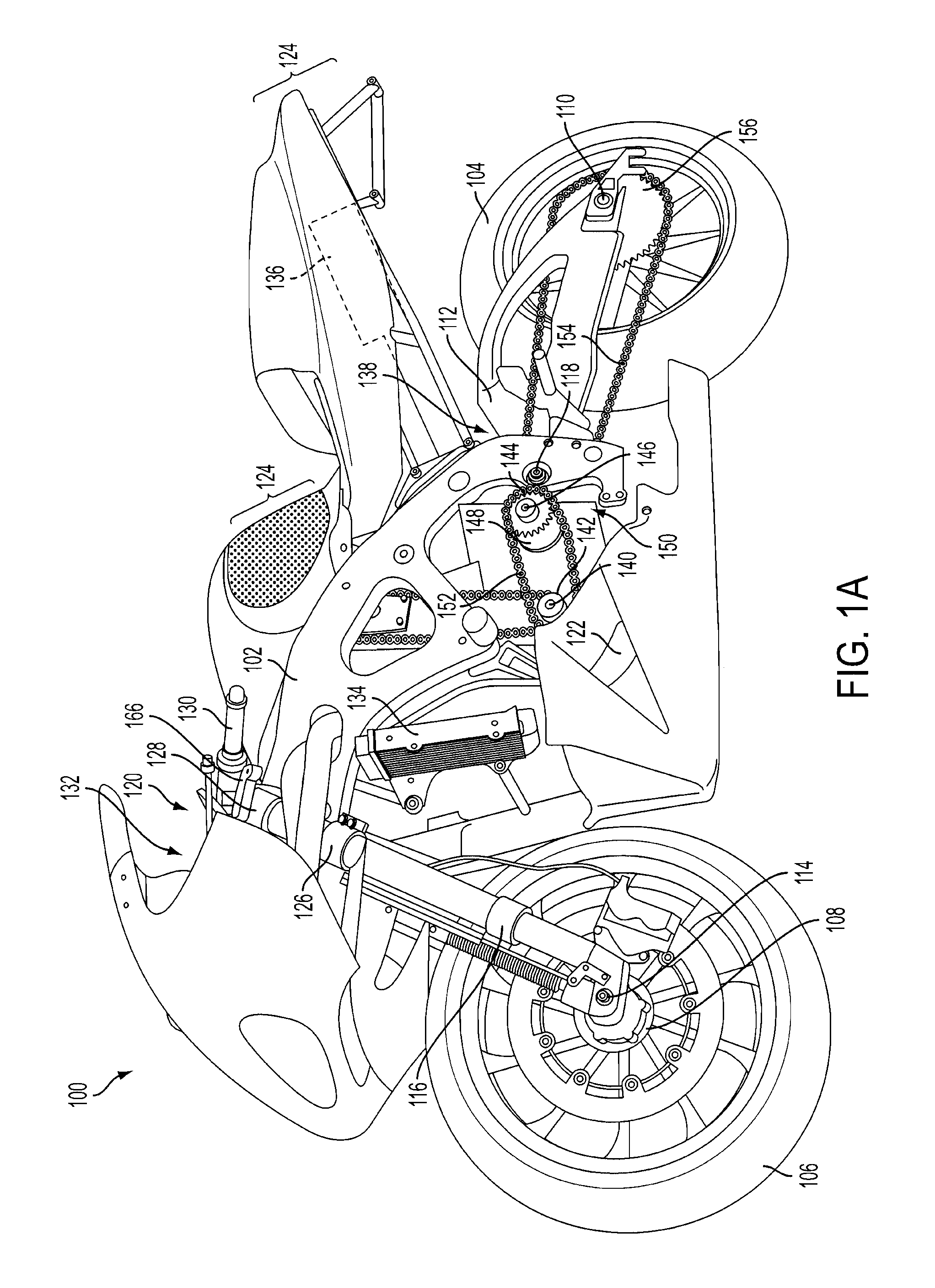
[0059]Embodiments relate to a kinetic energy recovery system and a motorcycle equipped with the same. It should be noted that for simplicity, the following paragraphs discuss embodiments relating to a motorcycle. This should not be viewed as limiting however, as the described KERS systems are designed for application with any two-wheeled or three-wheeled motorcycle and other vehicle. Accordingly, in addition to any type of motorcycle, the KERS systems described may also be applied to scooters, mopeds, and other two-wheel or three-wheel motorized bikes or trikes.

[0060]The energy recovery system according to exemplary embodiments may comprise a mechanical system, a hydraulic system, or a combination thereof. The mechanical system will be referred to as the mechanical KERS system. The hydraulic system will be referred to as the hydraulic KERS system.

[0061]Ex...


PUM


Abstract

A kinetic energy recovery system (“KERS system”) and motorcycle equipped with the same is disclosed. The KERS system may be mechanical, hydraulic, or a combination thereof. In an embodiment, motorcycle includes a rear wheel, an electric motor, a motor shaft, and a front wheel equipped with a wheel hub that includes a sprag clutch. The motor shaft can be fitted with a motor drive sprocket that drives a jackshaft chain that in turn drives a jackshaft input sprocket that is fitted to the jackshaft. Jackshaft input sprocket may be installed in conjunction with a sprag clutch that allows the rear wheel to free wheel during coasting while the front wheel KERS system is engaged. The motor harvests kinetic energy from the front wheel without simultaneously powering the rear wheel while the use of a geared dead zone allows the front and rear wheels to not lock together to improve safety.

Description


Claims


Application Information

Patent Timeline
Owner W MORRISON CONSULTING GRP
Why Eureka
Try Eureka