Power control circuit and method for stabilizing a power supply

Pending Publication Date: 2012-04-05
VERSITECH LTD
View PDF21 Cites 46 Cited by
  • Summary
  • Abstract
  • Description
  • Claims
  • Application Information

AI Technical Summary

Benefits of technology

[0011]On a smaller power scale, “single-phase” reactive power controllers have been proposed for use as dimming devices for lighting systems, as in patent GB2405540.B titled “Apparatus and Method for Providing Green Energy Saving and Dimming Control of Lamps and Electrical Lighting Systems” and GB2418786 titled “Dimmable lighting system”. In GB2405540.B, a reactive power controller with a control scheme as shown in FIG. 6 was used to reduce the input ac mains voltage for a lighting system. The idea is to create an auxiliary voltage Va using a “series” reactive power controller (shown in the dotted box) in FIG. 6 so that the output voltage of the controller Vo can be adjusted from the mains voltage Vs (typically 220V to 240V) down to a minimum voltage of 180V, which is the guaranteed minimum voltage for normal lighting system operation suggested by the manufacturers. The dimming level (or the value of the

Problems solved by technology

For such dynamically changing smart grids, it would be difficult to precisely predict the power flow within the power grids and therefore it would not be easy to centrally control the power flow within the smart grid systems.
The dynamic and changing nature of power generation in renewable energy sources such as wind (which is dependent on wind speeds) and solar (which is dependent on sunlight) make

Method used


Image

  • Power control circuit and method for stabilizing a power supply
  • Power control circuit and method for stabilizing a power supply
  • Power control circuit and method for stabilizing a power supply

Examples


Embodiment Construction

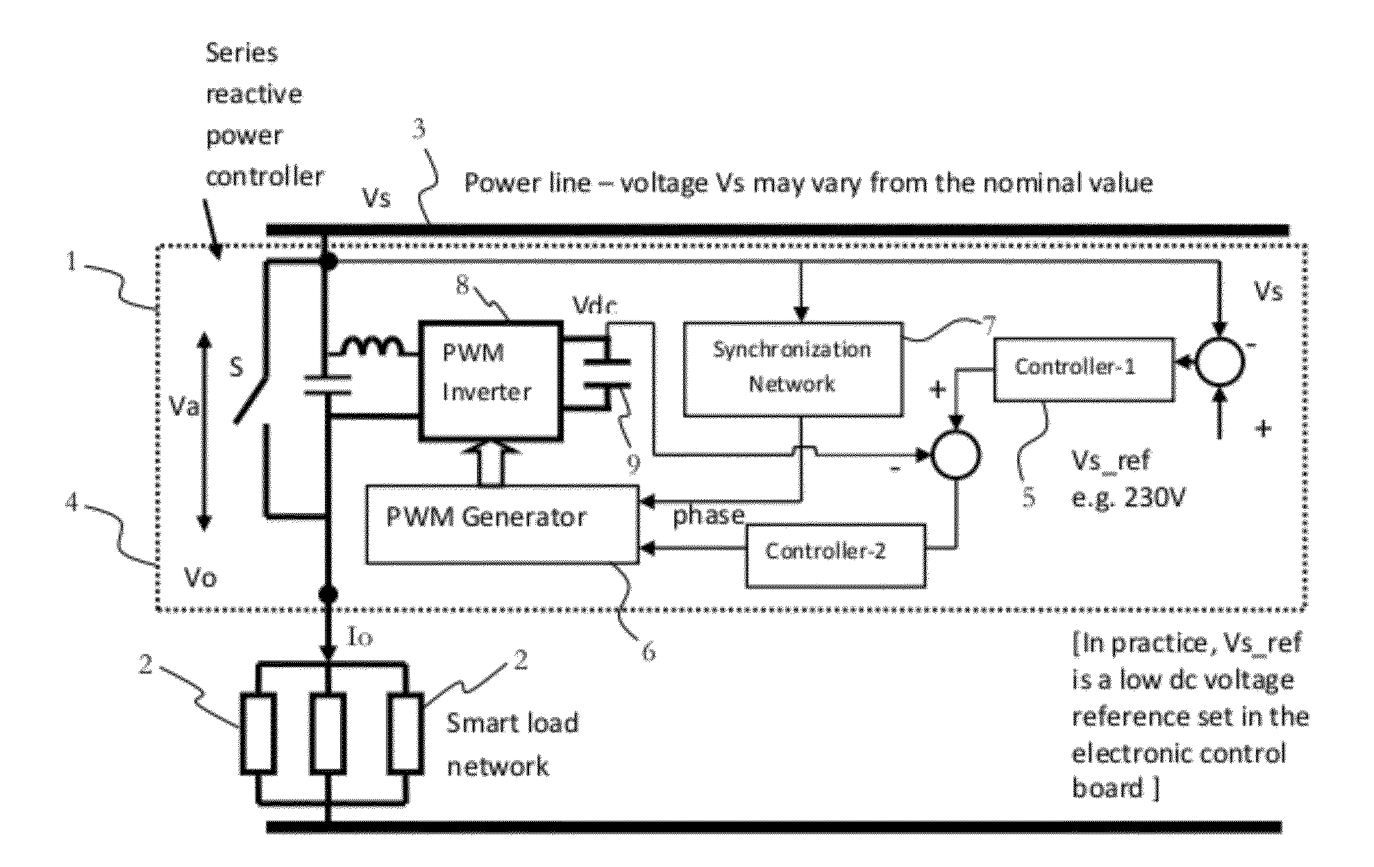
[0086]Referring to the figures, there is provided a power control circuit 1 connectable to a load 2 adapted to receive a power supply 3. The power control circuit 1 is adapted to absorb power from the power supply 3 and adapted to deliver power to the power supply 3 to stabilize at least one electrical parameter of the power supply 3. The power absorbed and delivered by the power control circuit 1 includes reactive power, or active power, or both.

[0087]In some embodiments, the power control circuit 1 is further adapted to deliver power to the load 2 to stabilize the at least one electrical parameter of the power supply 3.

[0088]Also in some embodiments, the at least one electrical parameter is voltage, with the power control circuit 1 maintaining the power supply 3 at a nominal supply voltage Vs. This nominal supply voltage can be any of the nominal mains voltages provided by power grids in various countries. For example, the nominal supply voltage can be 110V, 220V, 230V, or 240V. I...


PUM

PropertyMeasurementUnit
Angleaaaaaaaaaa
Poweraaaaaaaaaa
Electric potential / voltageaaaaaaaaaa

Abstract

The present invention provides a power control circuit connectable to a load adapted to receive a power supply, the power control circuit adapted to absorb power from the power supply and adapted to deliver power to the power supply to stabilize at least one electrical parameter of the power supply. The present invention also provides an associated method of stabilizing at least one electrical parameter of a power supply connectable to a load, the method including absorbing power from the power supply or delivering power to the power supply. The at least one electrical parameter of the power supply includes parameters such as voltage and frequency.

Description

CROSS-REFERENCE TO RELATED APPLICATIONS[0001]This application claims priority under 35 U.S.C. §119 to U.S. Provisional Application No. 61 / 389,489, filed Oct. 4, 2010, which is herein incorporated by reference in its entirety.FIELD OF THE INVENTION[0002]The present invention relates to power control circuits and methods for stabilizing power supplies, and in particular, but not limited to, circuits and methods of this type that are used with distributed loads connected to a dynamically changing power supply, such as that generated by dynamically changing renewable energy sources.BACKGROUND OF THE INVENTION[0003]The increasing need for expanding renewable energy sources such as wind, solar, geothermal and ocean wave energy have prompted new concerns about the uncertainties of future power grids, In traditional power systems, the amount and rate of power generation are well-controlled by the power stations, In the emerging grids, also called smart grids, more and more independent and d...

Claims


Application Information

Patent Timeline
IPC IPC(8): H05B3/02H05B37/02H02J3/00
CPCH02J3/24H02J3/18H02J3/1814Y02E40/22Y02E40/30H02J3/1842Y02E40/18H02J3/12Y02E40/10Y02E40/20H02J3/241H02J3/16
Inventor HUI, SHU YUEN RONLEE, CHI KWANWU, FELIX FULIH
Owner VERSITECH LTD
Why Eureka
Try Eureka