Fluid distribution features for climate controlled seating assemblies

a technology for climate control seats and fluid distribution features, which is applied in the direction of seat heating/ventilation devices, vehicle arrangements, chairs, etc., can solve the problems of uncomfortable occupants of vehicle seats, chairs or other seat assemblies situated in a relatively cold or hot environment, and achieve the effects of improving the efficiency of fluid modules, low pressure, and low contact area

Inactive Publication Date: 2012-04-05
GENTHERM INC
View PDF16 Cites 126 Cited by
  • Summary
  • Abstract
  • Description
  • Claims
  • Application Information

AI Technical Summary

Benefits of technology

[0013]According to some embodiments, a method of improving the efficiency of a fluid module included in a climate controlled seating assembly (e.g., vehicle seat, bed assembly, etc.) comprises recirculating at least a portion of air that has been environmentally conditioned (e.g., cooled, heated, dehumidified) by one or more fluid modules of the seating assembly back to an inlet of at least one fluid module, thereby lowering a ΔT of the fluid module receiving the recirculated air or other fluid. In some embodiments, recirculated air first enters a recess or other receiving portion along an outer portion of the seat assembly before being transferred to an inlet of a fluid module. In some embodiments, the region in which recirculated air enters the seat assembly (e.g., cushion, mattress, other support member, etc.) is generally a low pressure, low contact area. In some embodiments, the method comprises drawing recirculated air into an interior of the seat assembly via a bolster or other side portion of the cushion or other support member. In some embodiments, the method comprises drawing cooled and / or heated air from a fluid distribution region or member along an upper or front portion of the seat assembly, wherein said fluid distribution region or member is in fluid communication with an outlet of at least one fluid module of the seat assembly.

Problems solved by technology

For example, a vehicle seat, chair or other seat assembly situated in a relatively cold or hot environment can be uncomfortable to the occupant.

Method used


Image

  • Fluid distribution features for climate controlled seating assemblies
  • Fluid distribution features for climate controlled seating assemblies
  • Fluid distribution features for climate controlled seating assemblies

Examples


Embodiment Construction

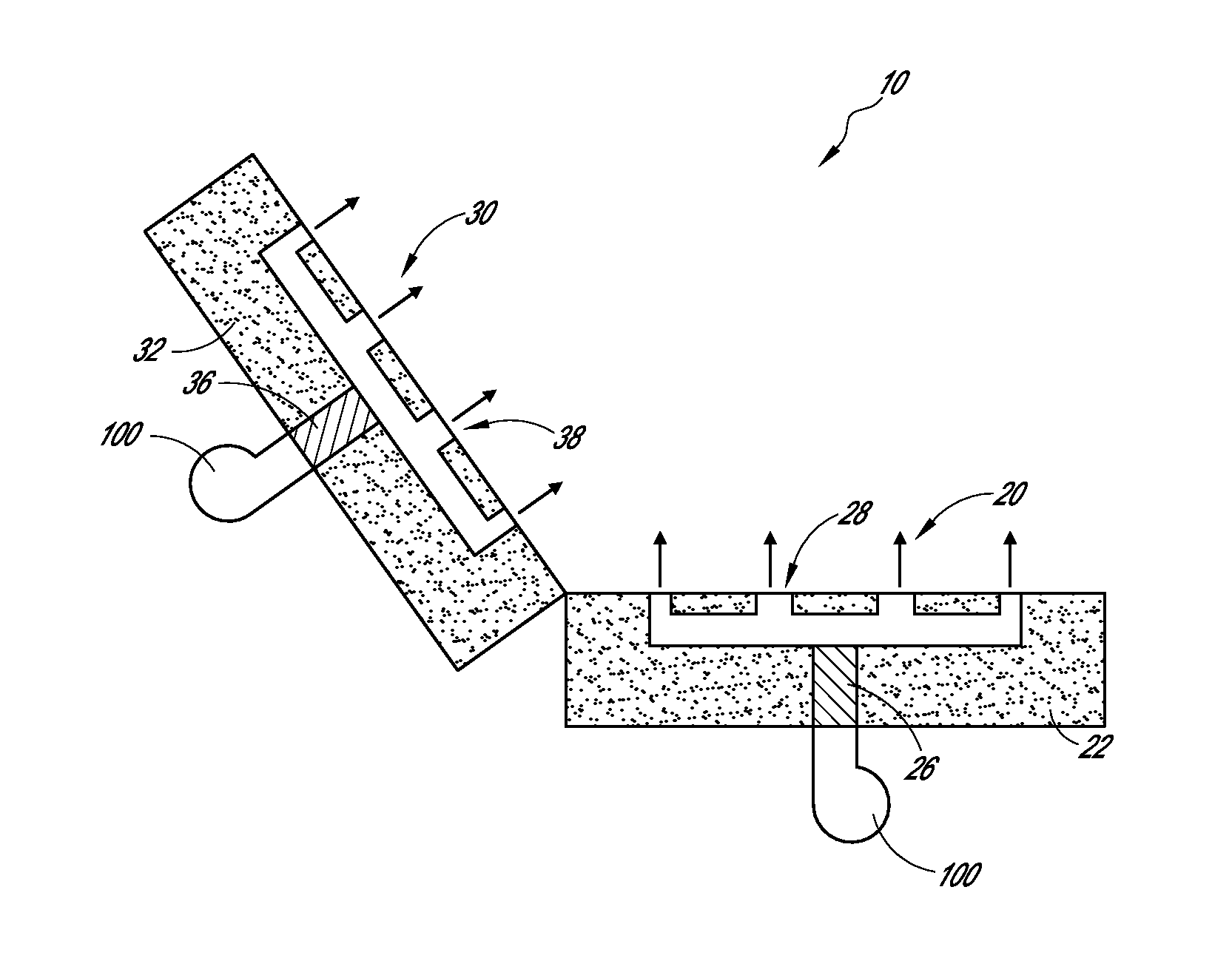
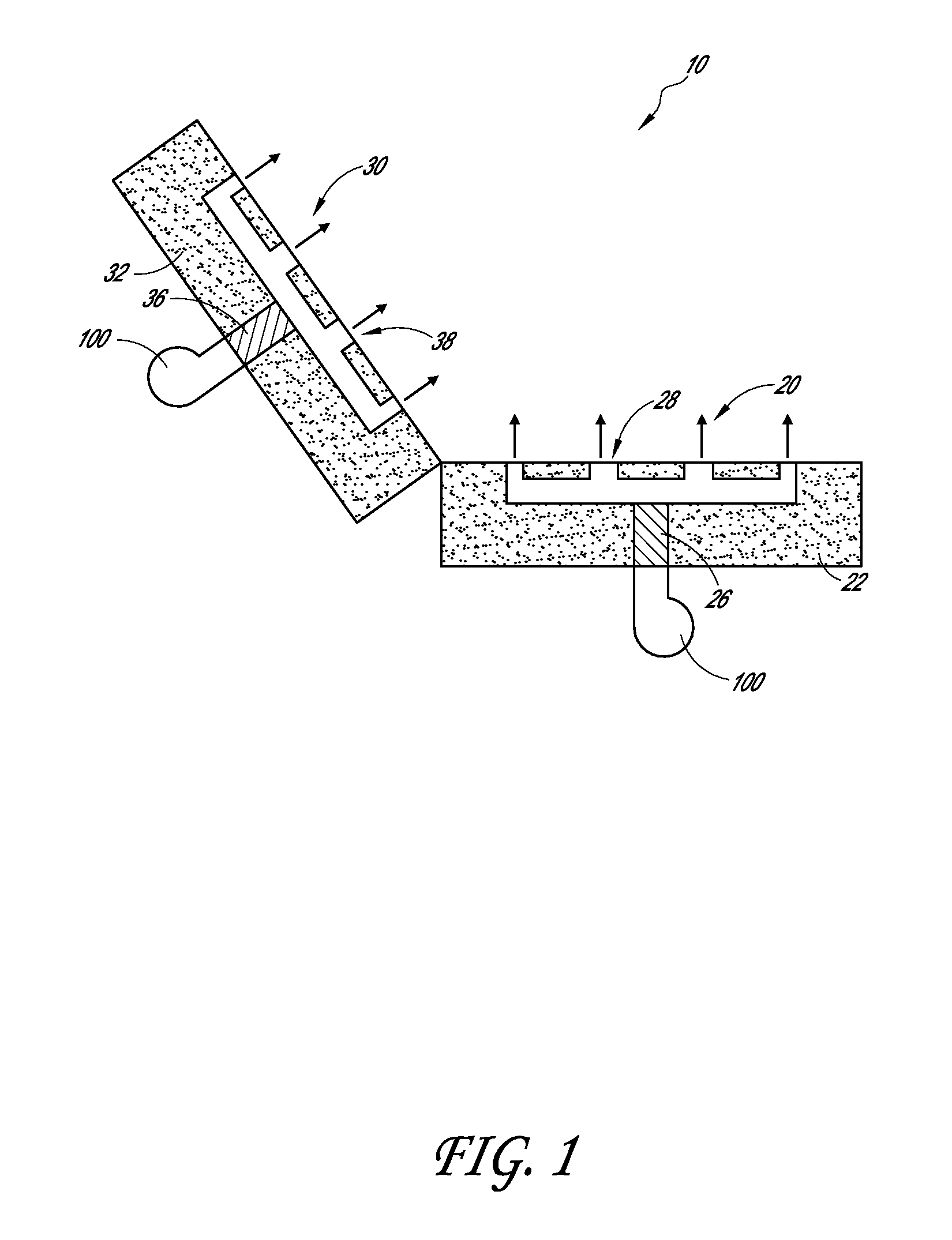
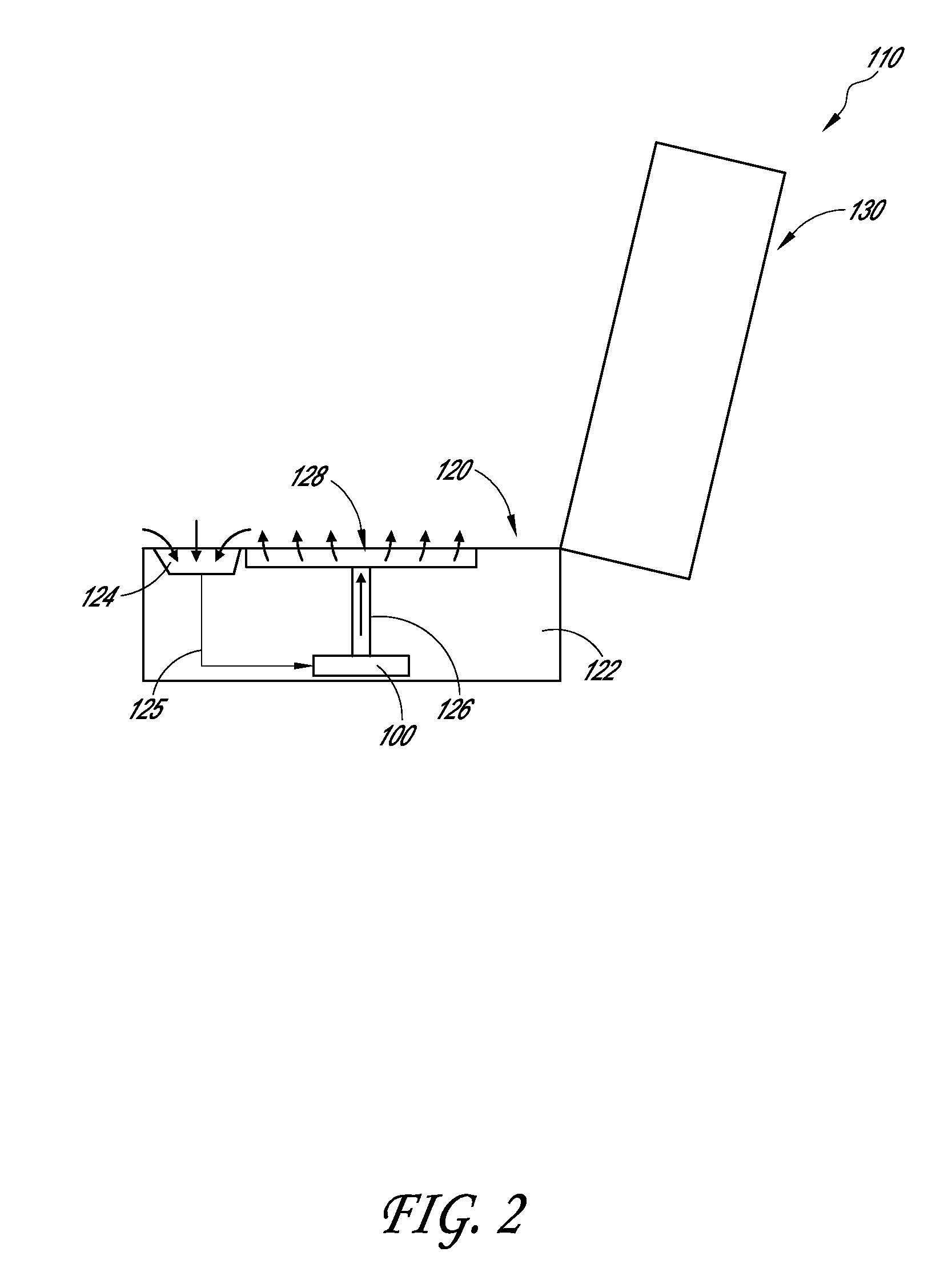
[0038]A variety of examples described below illustrate various configurations that may be employed to achieve desired improvements. The particular embodiments and examples provided herein are only illustrative and are not intended in any way to restrict the general inventions presented and the various aspects and features of these inventions. In addition, it should be understood that the terms cooling side, heating side, main side, waste side, cooler side and hotter side and the like do not indicate any particular temperature, but are relative terms. For example, the “hot,”“heating” or “hotter” side of a thermoelectric device or array may be at ambient temperature, with the “cold,”“cooling” or “cooler” side at a cooler temperature than ambient. Conversely, the “cold,”“cooling” or “cooler” side may be at ambient with the “hot,”“heating” or “hotter” side at a higher temperature than ambient. Thus, the terms are relative to each other to indicate that one side of the thermoelectric dev...


PUM


Abstract

According to some embodiments, a climate controlled seat assembly (e.g., a vehicle seat, a bed assembly, etc.) comprises a cushion or other support member positioned along a seat bottom portion or a seat back portion of the seat assembly, wherein the cushion includes a first surface configured to contact an occupant and a second surface generally opposite of the first surface. The cushion includes a cushion depth that generally extends between the first surface and the second surface of the cushion. The seat assembly further comprises at least one fluid passage positioned and routed at least partially through the cushion depth, wherein the fluid passage generally extends to the second surface of the cushion. Further, the seat assembly comprises at least one fluid module configured to selectively thermally and / or environmentally condition air and to transfer said thermally conditioned air through the fluid passage.

Description

CROSS REFERENCE TO RELATED APPLICATIONS[0001]This application claims the priority benefit under 35 U.S.C. §119(e) of U.S. Provisional Patent Application No. 61 / 377,892, filed Aug. 27, 2010, the entirety of which is hereby incorporated by reference herein.BACKGROUND[0002]1. Field of the Inventions[0003]This application generally relates to climate controlled seating assemblies, and more specifically, to channels, passages and other features in foam pads or other support structures of such seating assemblies.[0004]2. Description of the Related Art[0005]Temperature modified air for environmental control of an automobile, other vehicles or any other living or working space is typically provided to relatively extensive areas, such as an entire automobile interior, selected offices or suites of rooms within a building (e.g., houses, hospitals, office buildings, etc.) and the like. In the case of enclosed areas, such as automobiles, trains, airplanes, other vehicles, homes, offices, hospit...

Claims


Application Information

Patent Timeline
Patent Type & Authority Applications(United States)
IPC IPC(8): A47C7/74B60N2/56
CPCA47C7/744B60N2/5657B60N2/565B60N2/5642
Inventor BRYKALSKI, MICHAELMANUEL, RAYMUNDWOLAS, SCOTT
Owner GENTHERM INC
Why Eureka
Try Eureka