Eureka AIR delivers breakthrough ideas for toughest innovation challenges, trusted by R&D personnel around the world.

Integrated MOSFET Current Sensing for Fuel-Gauging

Active Publication Date: 2012-04-05
MAXIM INTEGRATED PROD INC
View PDF3 Cites 0 Cited by
  • Summary
  • Abstract
  • Description
  • Claims
  • Application Information

AI Technical Summary

Problems solved by technology

This extra sense element, typically a small resistor, adds power loss during both battery charging and discharging, proportional to the voltage and current through the battery current sense element.
All of these devices must be capable of conducting the maximum currents allowed, and accordingly are both relatively large, and in the case of the sense resistors, relatively expensive because of their capacity and accuracy requirements.
Further, of course, that many switches and sense resistors in series with particularly the charger is a significant source of heating and power loss, and for those devices actually packaged in the battery pack, the voltage drop across the switches and sense resistor will require a higher battery voltage before system shutdown, thereby limiting the discharge voltage to a higher voltage and thus the useful capacity of the battery to a lower capacity.

Method used


Image

  • Integrated MOSFET Current Sensing for Fuel-Gauging
  • Integrated MOSFET Current Sensing for Fuel-Gauging
  • Integrated MOSFET Current Sensing for Fuel-Gauging

Examples


Embodiment Construction

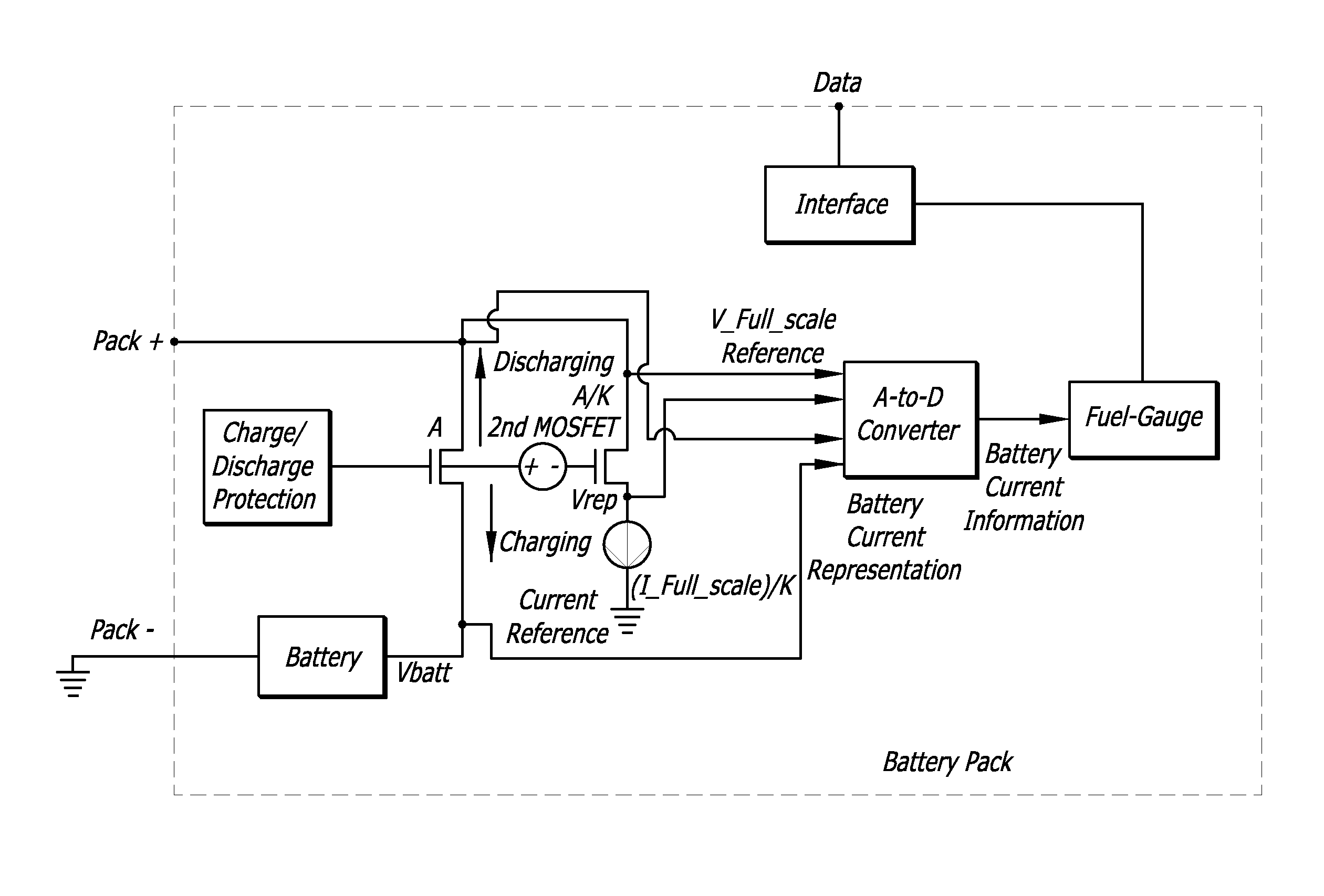
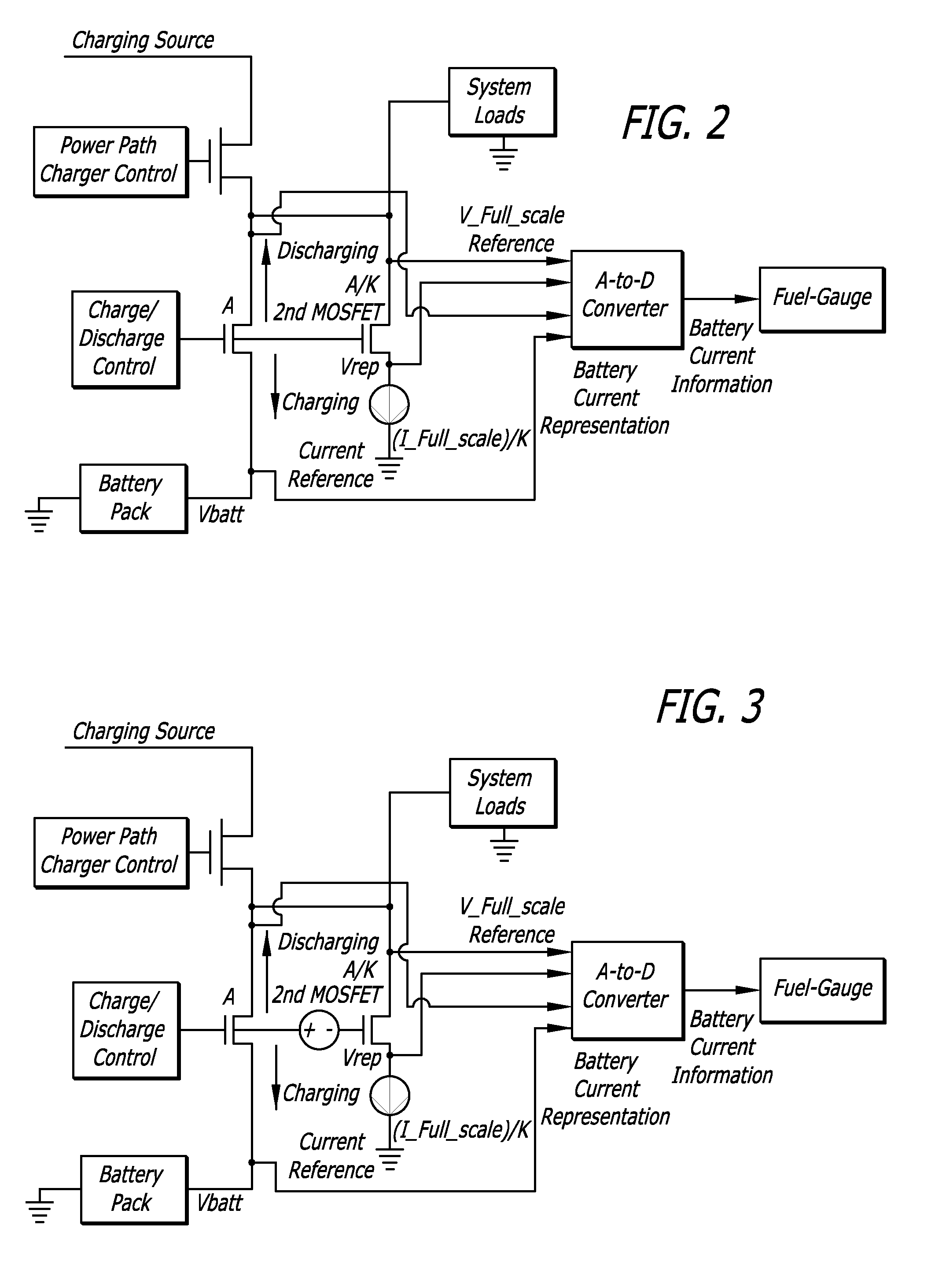
[0014]Some embodiments of the present invention measure the battery charging and discharging current under all conditions while removing the need for, and eliminating, the extra sense element in series with the battery current. This reduces the power dissipation, resulting in a longer battery discharge time when the battery is powering a load, and a lower device temperature and power requirements when charging the battery. The battery current measurement is accomplished by:

[0015]1. Creating a reference voltage that represents the voltage that will occur across the battery charge / discharge power MOSFET at the full-scale current (V_Full_scale), i.e. the maximum charge / discharge current that will be encountered.

[0016]2. Using a switch-capacitor or other analog-to-digital conversion technique to convert the voltage across the battery charge / discharge power MOSFET, as a fraction of the V_Full_scale reference voltage, into a digital representation.

[0017]This digital representation is then...


PUM


Abstract

Integrated MOSFET current sensing for fuel-gauging. A 1st MOSFET through which the current is to be sensed is coupled to a 2nd MOSFET of the same type, the 2nd MOSFET being biased to have the same resistance as the 1st MOSFET. The 2nd MOSFET has a much smaller area than the 1st MOSFET, and is coupled to a current source representing a maximum current through the 1st MOSFET. The voltage across the 1st MOSFET relative to the voltage across the 2nd MOSFET provides a measure of the current through the 1st MOSFET. Various embodiments are disclosed, including embodiments in battery packs to eliminate the need for additional and expensive external components.

Description

CROSS-REFERENCE TO RELATED APPLICATIONS[0001]This application claims the benefit of U.S. Provisional Patent Application No. 61 / 385,090 filed Sep. 21, 2010 and U.S. Provisional Patent Application No. 61 / 385,475 filed Sep. 22, 2010.BACKGROUND OF THE INVENTION[0002]1. Field of the Invention[0003]The present invention relates to the field of fuel gauging for monitoring battery charge or battery state of charge.[0004]2. Prior Art[0005]Fuel-gauging technology can both predict and increase battery life, by monitoring the battery characteristics and state of charge, and making adjustments to the charging parameters as needed. One of the important input data needed for most fuel-gauge algorithms is an accurate sampling of battery current. The high accuracy required for the battery current measurement, and the need to measure the battery charge and discharge current under all conditions, has previously required an extra sense element inside the battery charge and discharge paths. This extra s...

Claims


Application Information

Patent Timeline
IPC IPC(8): G01N27/49
CPCG01R31/3686G01R19/0092H01M10/48Y02E60/10
Inventor HARRINGTON, DAVIDVANDEN WYMELENBERG, JOSEPH B.PEAK, JR., MARVIN LYLEWORTHAM, JASON ALLEN
Owner MAXIM INTEGRATED PROD INC
Why Eureka
Eureka Blog
Learn More