
Liquid crystal display and signal transmission apparatus thereof

Inactive Publication Date: 2012-04-05
AU OPTRONICS CORP
View PDF4 Cites 3 Cited by
  • Summary
  • Abstract
  • Description
  • Claims
  • Application Information

AI Technical Summary

Benefits of technology

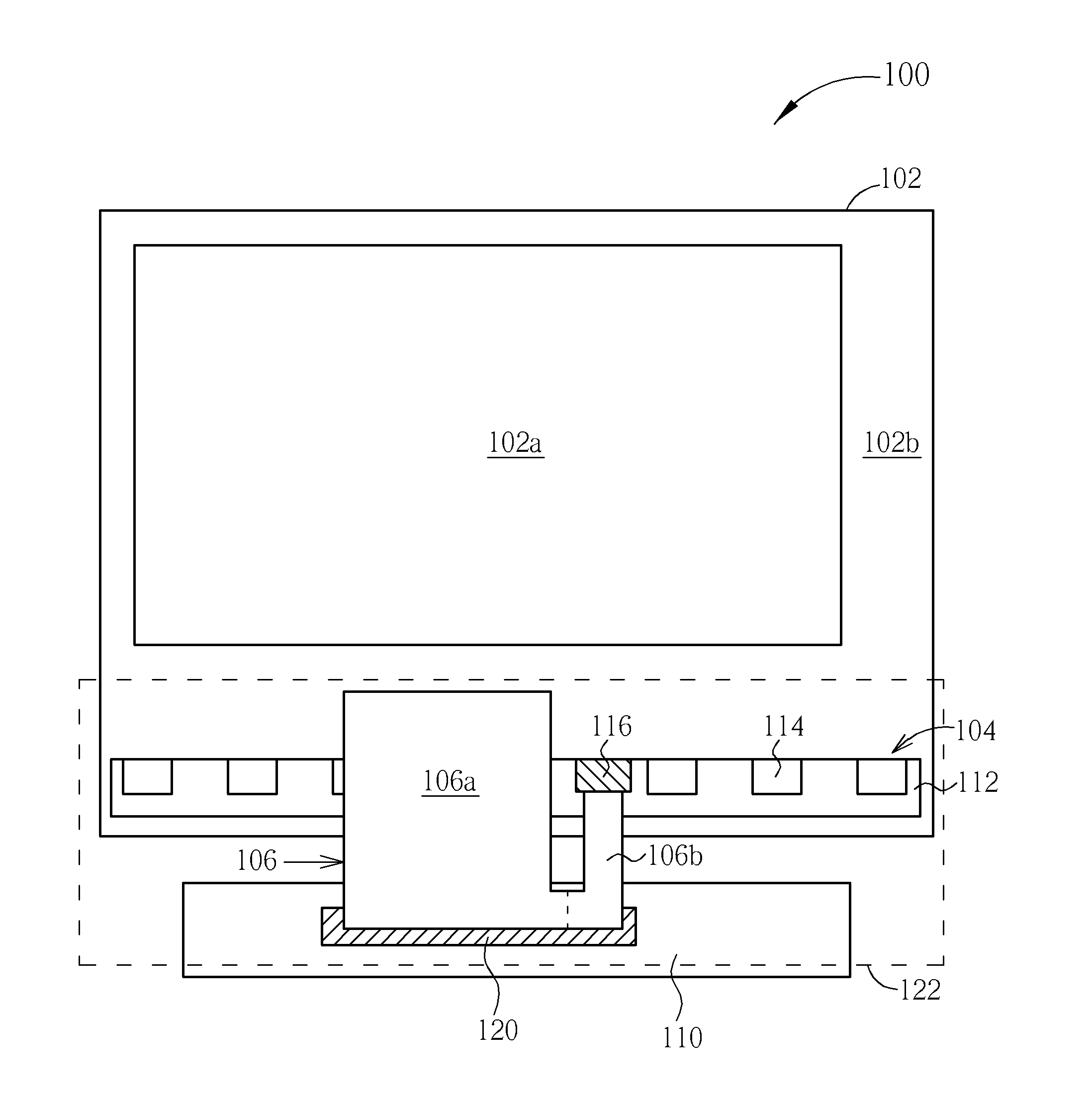
[0009]It is therefore an objective of the present invention to provide a liquid crystal display and a signal transmission apparatus thereof to raise the utility of circuit board material for manufacturing the light-source circuit board of the light-source module and reduce the complication of assembling the flexible circuit board and the light-source circuit board.
[0012]The connector is disposed on the light-source circuit board in the liquid crystal display of the present invention, so that the light-source circuit board does not require an extra connecting part being extended to electrically connect the control circuit board. Thus, the light-source circuit board has a strip formation, so that the utility of the circuit board material for manufacturing the light-source circuit board can be effectively raised, and the material cost can be reduced.

Problems solved by technology

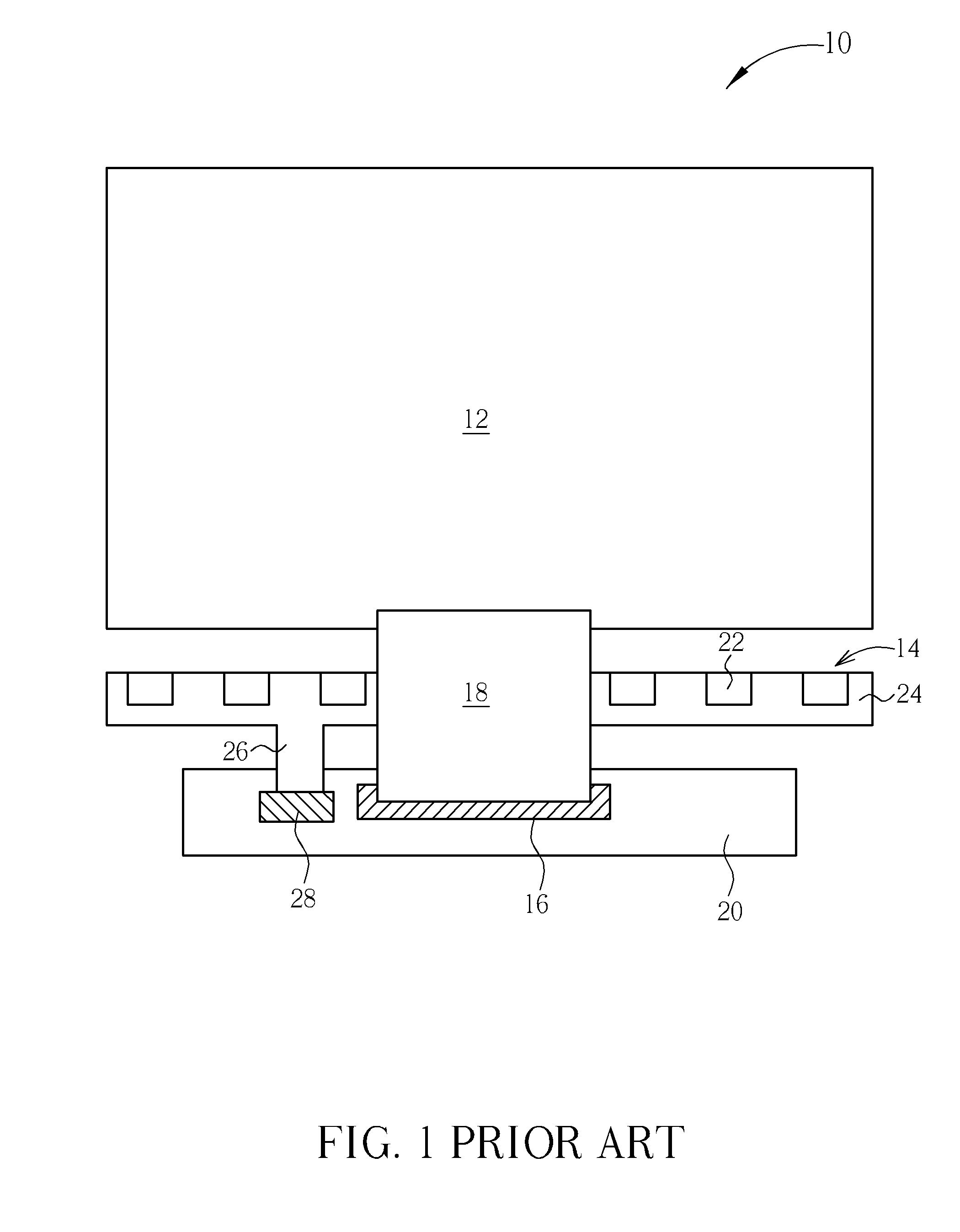
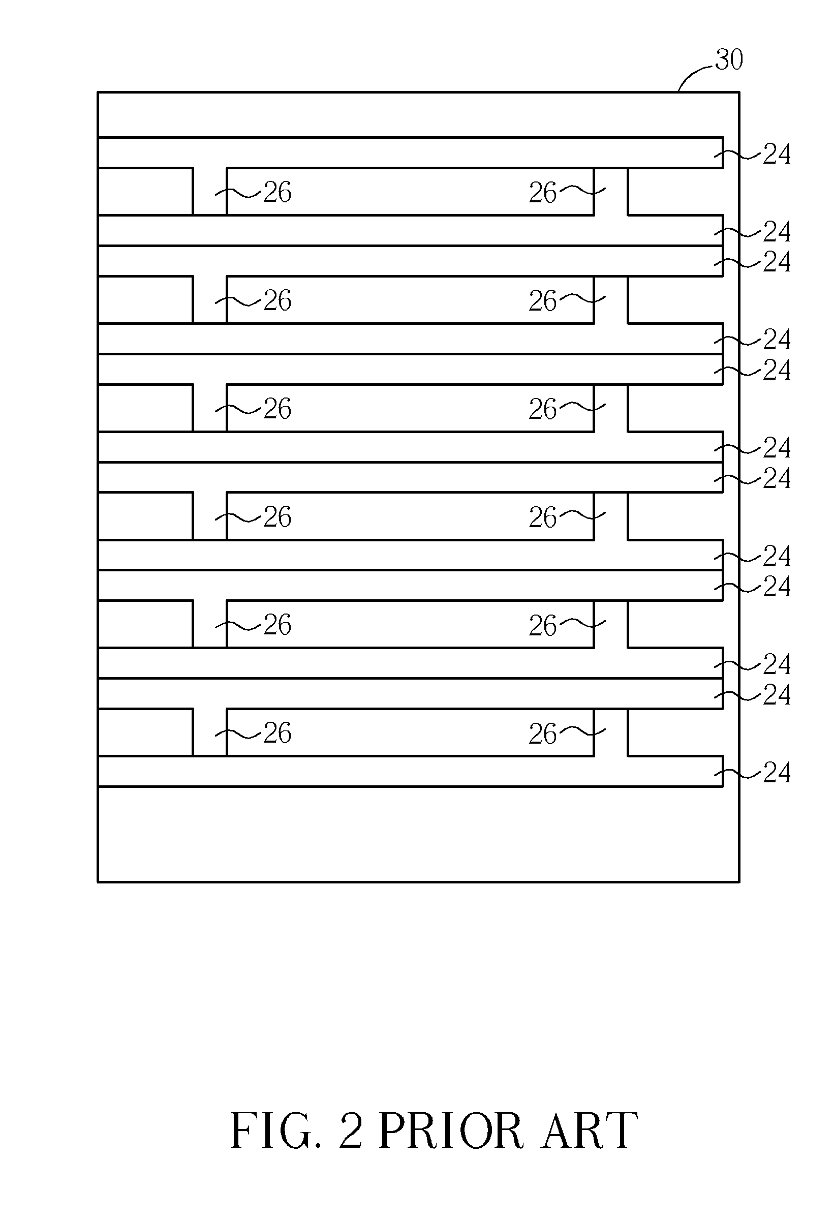
Thus, a circuit board material for manufacturing the light-source circuit board 24 with the T-shaped formation cannot be full utilized, and the rest flexible sheet material is wasted.
Therefore, the provided circuit board material 30 only can be divided into twelve complete light-source circuit boards 24, and a part of the circuit board material 30 between the adjacent light-source circuit boards 24 still is unused, so that utility of the circuit board material 30 is not enough, which results in the problem of waste of materials.
For this reason, using two connection assembling methods of the connector 28 and conductive adhesive 16 simultaneously in the control circuit board 20 not only is complicated and difficult but also usually results in damages of the connector 28 or the conductive adhesive 16 during assembling the connection due to the problem of the process sequence, and the manufacturing cost is also increased.

Method used


Image

  • Liquid crystal display and signal transmission apparatus thereof
  • Liquid crystal display and signal transmission apparatus thereof
  • Liquid crystal display and signal transmission apparatus thereof

Examples


Embodiment Construction

[0019]To provide a better understanding of the presented invention, preferred embodiments will be made in details. The preferred embodiments of the present invention are illustrated in the accompanying drawings with numbered elements.

[0020]Refer to FIG. 3, which is a schematic diagram illustrating a liquid crystal display according to a first preferred embodiment of the present invention. As shown in FIG. 3, the liquid crystal display 100 of this preferred embodiment includes a liquid crystal panel 102, a light-source module 104, a transmission device 106, and a control circuit board 110. The control circuit board 110 of this preferred embodiment is used for providing a display signal to the liquid crystal panel 102 and providing a light-source control signal to the light-source module 104, and the control circuit board 110 can be a rigid or flexible circuit board having a control system, but is not limited herein. Or, the control circuit board 110 is electrically connected to a con...


PUM


Abstract

The present invention provides a liquid crystal display, including a liquid crystal panel, a light-source module, and a transmission device. The light-source module includes a light-source circuit board, at least one light-emitting device, and a connector. The light-emitting device is disposed on the light-source circuit board and electrically connected to the light-emitting device through the light-source circuit board. The transmission device is electrically connected to the liquid crystal display and the connector, so that a display signal is transmitted to the liquid crystal panel through the transmission device, and a light-source control signal is transmitted to the light-emitting device sequentially through the transmission device, the connector and the light-source circuit board.

Description

BACKGROUND OF THE INVENTION[0001]1. Field of the Invention[0002]The present invention relates to a liquid crystal display and a signal transmission apparatus thereof, and more particularly, to a liquid crystal display and a signal transmission apparatus thereof using a connector to transmit a light-source control signal.[0003]2. Description of the Prior Art[0004]The liquid crystal display (LCD) panel is characterized by light weight, low power consumption, and low radiation, and is widely applied in portable electronic products such as notebook computers and personal digital assistant (PDAs). LCD monitors are so useful that cathode ray tube (CRT) monitors are being replaced. It is well known that incident light will produce different polarization or refraction when the alignments of liquid crystal molecules are different. Accordingly, the LCD utilizes the liquid crystal molecules with different alignments to control the light transmittance of each pixel unit, so that the LCD is enab...

Claims


Application Information

Patent Timeline
IPC IPC(8): G09G5/10
CPCG02F2001/133612G02F1/133602G02F1/133612
Inventor LEE, KENG-YILIN, SHIH-YAO
Owner AU OPTRONICS CORP
Learn More