
Milli-meter-wave-wireless-interconnect (m2w2 - interconnect) method for short-range communications with ultra-high data capability

Active Publication Date: 2012-04-05
RGT UNIV OF CALIFORNIA
View PDF7 Cites 63 Cited by
  • Summary
  • Abstract
  • Description
  • Claims
  • Application Information

AI Technical Summary

Benefits of technology

[0009]To overcome the limitations in the prior art described above, and to overcome other limitations that will become apparent upon reading and understanding the present specification, the present invention discloses a millimeter wave wireless (M2W2

Problems solved by technology

On-chip interconnects, especially for multi-processor chips and network-on-a-chip, have been projected as the limiting factor in terms of bandwidth, power and latency.
However, on-chip interconnects remain non-scalable and non-reconfigurable.
However, this on-chip antenna required the use of a phase and frequency synchronous modulation scheme, such as binary phase-shifted-keying (BPSK), which increased the complexity of the architecture and overall power consumption.

Method used


Image

  • Milli-meter-wave-wireless-interconnect (m2w2 - interconnect) method for short-range communications with ultra-high data capability
  • Milli-meter-wave-wireless-interconnect (m2w2 - interconnect) method for short-range communications with ultra-high data capability
  • Milli-meter-wave-wireless-interconnect (m2w2 - interconnect) method for short-range communications with ultra-high data capability

Examples


Embodiment Construction

[0023]In the following description of the preferred embodiment, reference is made to the accompanying drawings which form a part hereof, and in which is shown by way of illustration a specific embodiment in which the invention may be practiced. It is to be understood that other embodiments may be utilized and structural changes may be made without departing from the scope of the present invention.

Technical Disclosure

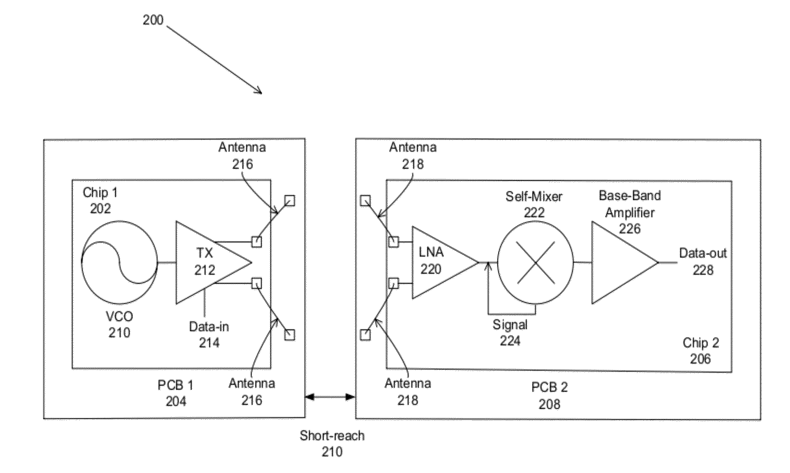
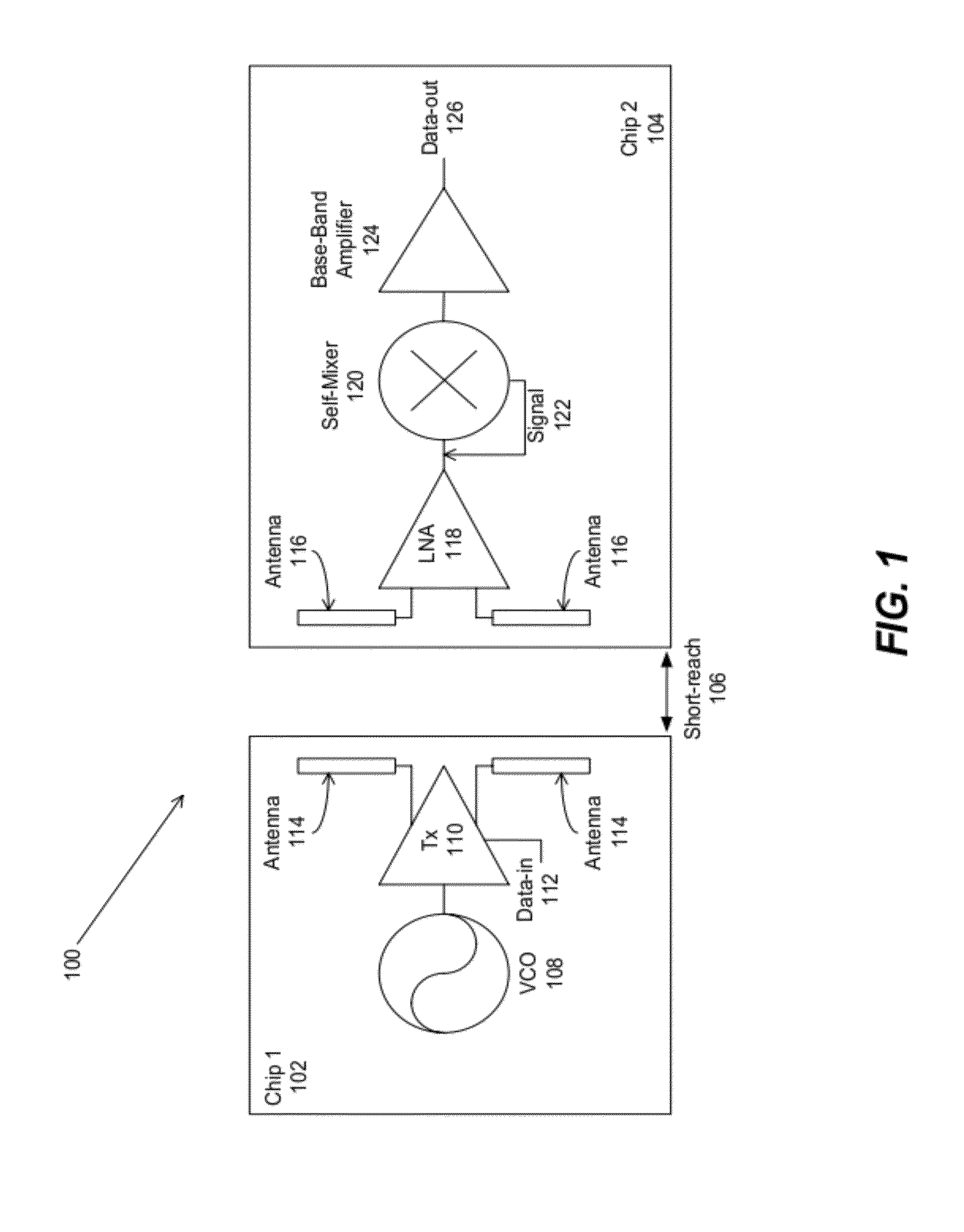
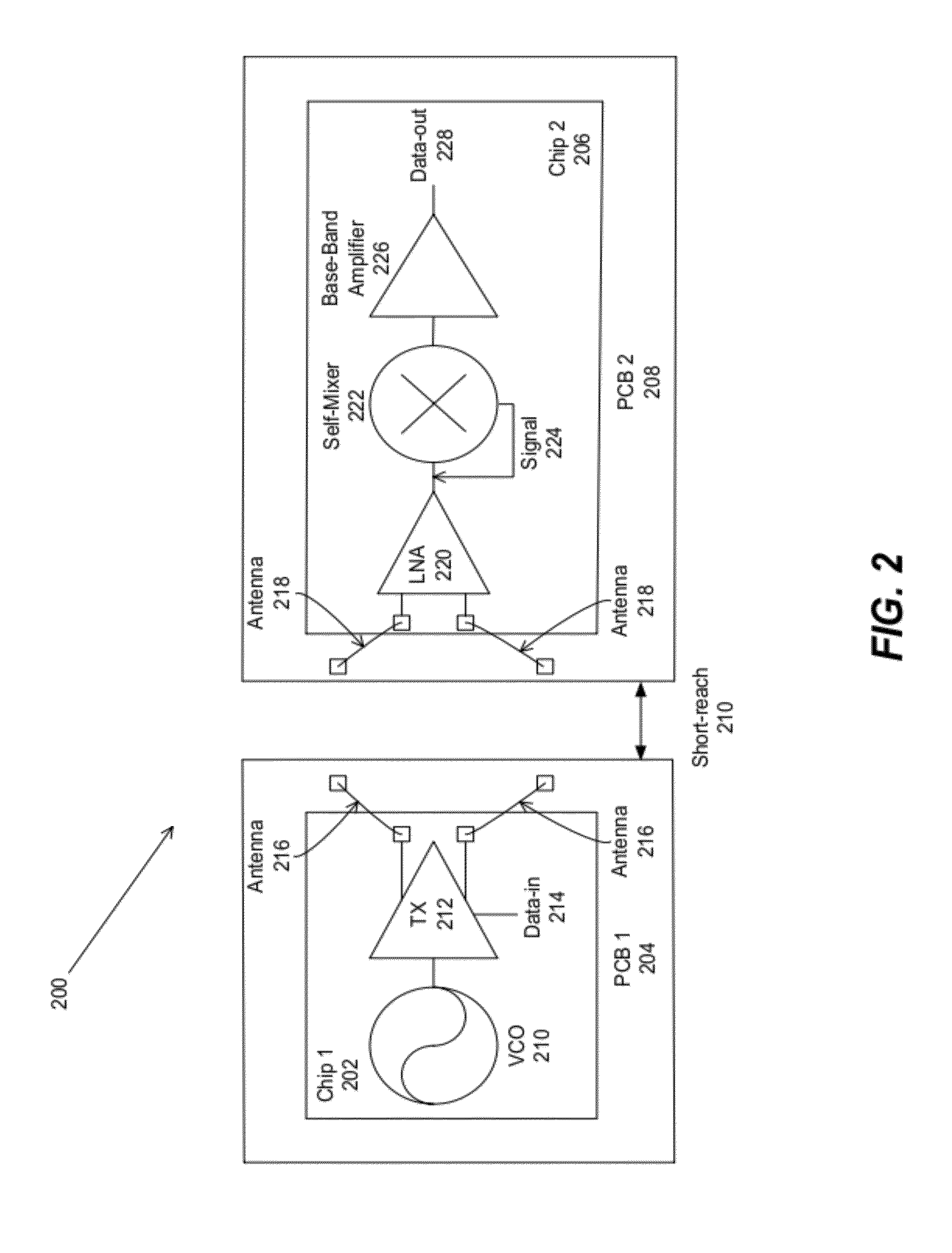
[0024]The present invention comprises a wireless interconnect for transmitting and receiving signals at specified frequencies for short-range communication with high data rate capability, comprising the M2W2 interconnect, where the specified frequencies are millimeter-wave frequencies, using an asynchronous modulation scheme and differential signaling architecture. The M2W2 interconnect transmits data wirelessly, in contrast to previous implementations of RF-I (radio frequency interconnects) that utilize a controlled-impedance transmission medium [2]. Moreover, the speci...


PUM


Abstract

A millimeter wave wireless (M2W2) interconnect is used for transmitting and receiving signals at millimeter-wave frequencies for short-range wireless communication with high data rate capability. The transmitter and receiver antennae may comprise an on-chip differential dipole antenna or a bond wire differential dipole antenna. The bond wire differential dipole antenna is comprised of a pair of bond wires connecting between a pair of pads on an integrated circuit (IC) die and a pair of floating pads on a printed circuit board (PCB).

Description

CROSS REFERENCE TO RELATED APPLICATION[0001]This application claims the benefit under 35 U.S.C. Section 119(e) of co-pending and commonly-assigned U.S. Provisional Patent Application Ser. No. 61 / 185,946, filed on Jun. 10, 2009, by Sai-Wang Tam and Mau-Chung F. Chang, entitled “MILLI-METER-WAVE-WIRELESS-INTERCONNECT (M2W2-INTERCONNECT) METHOD FOR SHORT-RANGE COMMUNICATIONS WITH ULTRA-HIGH DATA RATE CAPABILITY,” attorneys' docket number 30435.209-US-P1 (2009-445-1), which application is incorporated by reference herein.BACKGROUND OF THE INVENTION[0002]1. Field of the Invention[0003]This invention relates to a millimeter wave wireless (M2W2) interconnect method for short range communications with ultra-high data rate capability.[0004]2. Description of the Related Art[0005](Note: This application references a number of different publications as indicated throughout the specification by one or more reference numbers within brackets, e.g., [x]. A list of these different publications order...

Claims


Application Information

Patent Timeline
IPC IPC(8): H04L5/16
CPCH04B5/02H04B5/0031H01L2224/49171H04B5/72H04B5/48
Inventor TAM, SAI-WANGCHANG, MAU-CHUNG FRANK
Owner RGT UNIV OF CALIFORNIA
Features
  • Generate Ideas
  • Intellectual Property
  • Life Sciences
  • Materials
  • Tech Scout
  • Unparalleled Data Quality
  • Higher Quality Content
  • 60% Fewer Hallucinations
Learn More