Device for torque vectoring

a technology of torque vectoring and torque, applied in mechanical equipment, transportation and packaging, transportation and packaging, etc., can solve the problems of heavy devices having a relatively high power consumption, heavy arrangements, and heavy devices, and achieve the effects of reducing energy loss, reducing energy loss, and high losses

Active Publication Date: 2012-04-05
BORGWARNER TORQ TRANSFER SYSTEMS AB
View PDF11 Cites 11 Cited by
  • Summary
  • Abstract
  • Description
  • Claims
  • Application Information

AI Technical Summary

Benefits of technology

[0016]The differential mechanism may comprise a differential, which is advantageous in that readily available components may be used, and the electrical motor may be connected to the first drive shaft and said second drive shaft by means of a planetary gear set, wherein the electrical motor is driving a sun gear, the first drive shaft is connected to a ring gear, and wherein the second drive shaft is connected to planetary gears. In such embodiment, the gear ratios of the planetary gear set may be designed such that no torque is transmitted through the planetary gear set when the electrical motor is deactivated. Further, the gear ratios of the planetary gear set may be designed such that the electrical motor is standing still when the first drive shaft and the second drive shaft are rotating at the same rotational speed. This means that possible loss of energy is reduced.
[0017]The differential mechanism may comprise a first planetary gear set connected to the first drive shaft, and a second planetary gear set connected to the second drive shaft, and said electrical motor may be connected to said first drive shaft and said second drive shaft by means of two gears rotating at different directions, wherein said gears are connected to each other by means of a shaft extending along the axle. Hence, the shaft connecting the gears is designed to stand still when the first drive shaft and the second drive shaft are rotating at the same rotational speed. Further, the shaft is designed to rotate at a speed being proportional to the differential rotational speed between the first drive shaft and the second drive shaft. Since the differential rotational speed at most times will be zero, or very close to zero, energy losses will be reduced.
[0018]The electrical motor may be connected to a clutch configured to decouple the rotational axis of the electrical motor from said differential mechanism. The clutch may be automatically decoupled when the rotational speed of said clutch is exceeding a predetermined threshold value. Alternately or additionally, the control means may be configured to cause automatic decoupling of said clutch based on an analysis of at least one of said plurality of variables representing the current vehicle state. This is advantageous in that the electrical motor is protected against overload, e.g. in transient vehicle conditions such as ESP intervention.
[0019]Said propulsion motor may be connected to a mechanical disconnect unit configured to disconnect the propulsion motor from said axle. Alternately or additionally, said control means may be configured to cause automatic actuation of said mechanical disconnect unit based on an analysis of at least one of said plurality of variables representing the current vehicle state, so as to disconnect the propulsion motor from said axle. This is further advantageous in that high losses, occurring from drag torque and field weakening during high speed, may be reduced or eliminated.
[0020]Said power electronics unit may be further configured to control the energy flow between the accumulator and the propulsion motor by supplying drive currents to said propulsion motor via the accumulator, and the power electronics unit may be further configured to allow reverse energy flow for charging the accumulator during braking of the vehicle. Regenerative braking may thus be used to decrease the energy consumption of the vehicle.

Problems solved by technology

In such arrangements being both heavy and expensive, torque vectoring devices are arranged at either side of the central differential for the two drive shafts.
Hence, when a differential rotational speed between two wheels is requested the prior art devices are affecting the rotational speed relative the absolute rotational speed, leading to heavy devices having a relatively high power consumption.

Method used


Image

  • Device for torque vectoring
  • Device for torque vectoring
  • Device for torque vectoring

Examples


Embodiment Construction

[0034]Several embodiments of the present invention will be described in more detail below with reference to the accompanying drawings in order for those skilled in the art to be able to carry out the invention. The invention may, however, be embodied in many different forms and should not be construed as limited to the embodiments set forth herein. Rather, these embodiments are provided so that this disclosure will be thorough and complete, and will fully convey the scope of the invention to those skilled in the art. The embodiments do not limit the invention, but the invention is only limited by the appended patent claims. Furthermore, the terminology used in the detailed description of the particular embodiments illustrated in the accompanying drawings is not intended to be limiting of the invention.

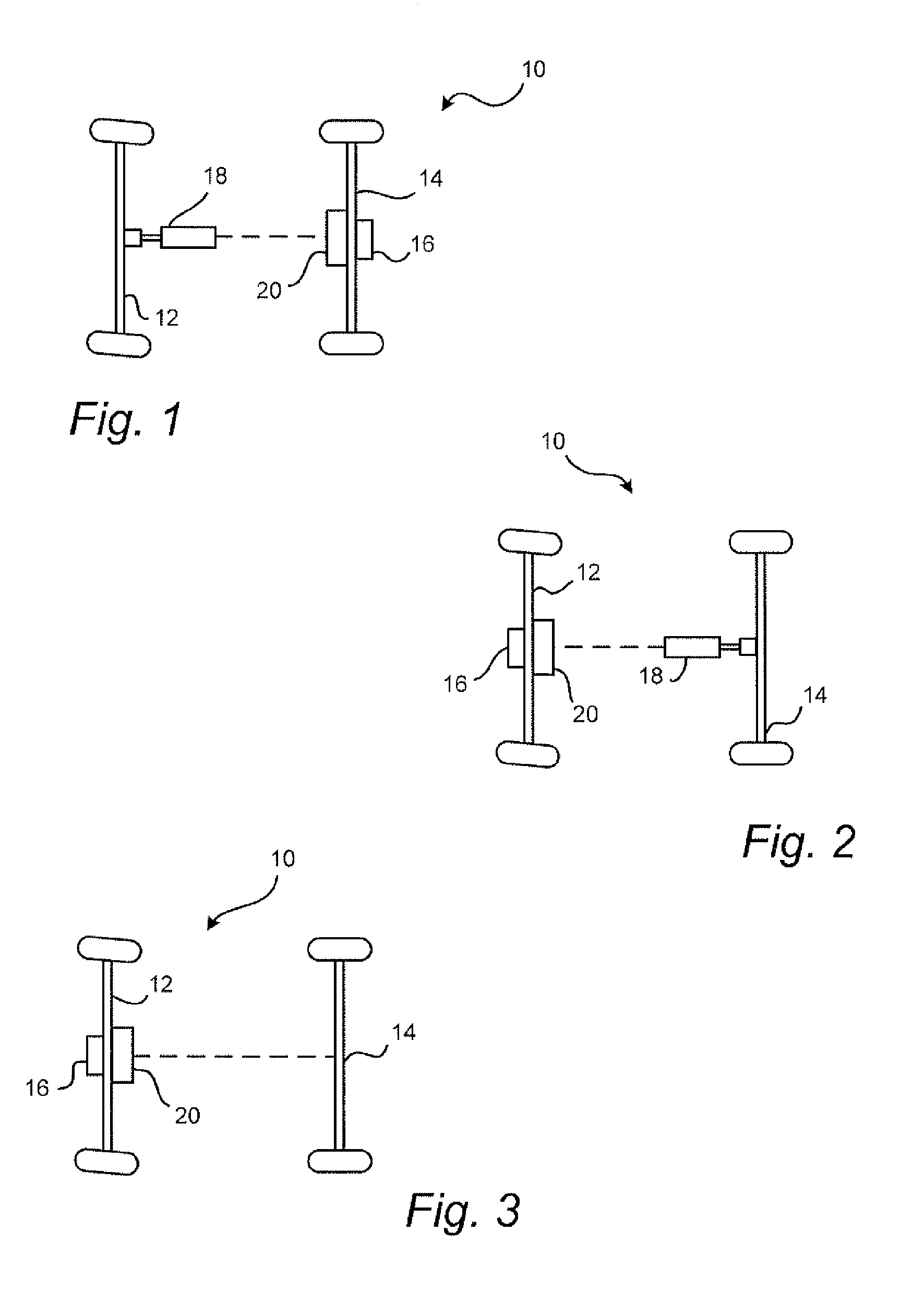
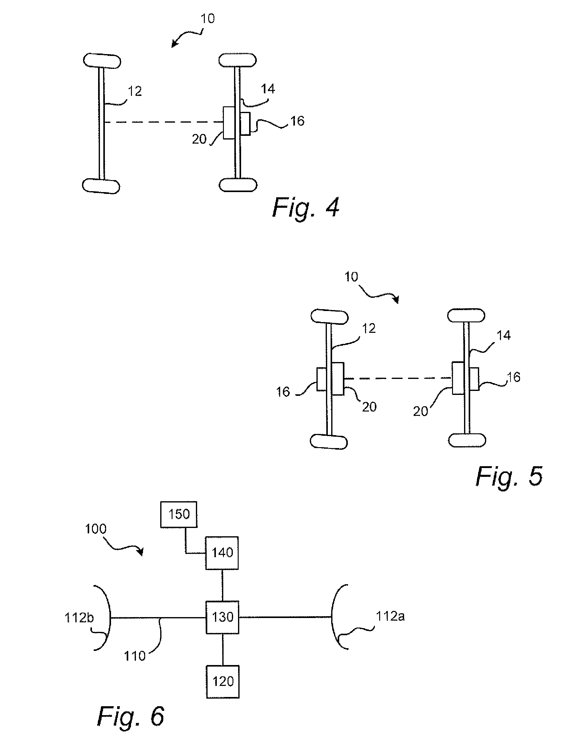
[0035]Examples of drive line configurations of a vehicle are shown in FIGS. 1 to 6. In these embodiments, the vehicle 10 has a front axle 12 being connected to a rear axle 14, and a to...


PUM


Abstract

A device for torque vectoring in a wheeled vehicle is presented. The device includes a differential mechanism arranged on an axle having a first drive shaft and a second drive shaft, an electrical power source connected to an electrical motor, the electrical motor being connectable to the axle for torque vectoring between the first drive shaft and the second drive shaft, and control means connected to the power source and configured to receive a plurality of variables representing the current vehicle state and to determine drive currents being dependent on the variables, wherein the drive currents are supplied to the electrical motor from the power source for introducing a torque increase to either one of the first or second drive shafts and a corresponding torque decrease to the other one of the first or second drive shafts.

Description

CROSS-REFERENCE TO RELATED APPLICATIONS[0001]The present application is a continuation of pending International patent application PCT / SE2010 / 050066 filed on Jan. 25, 2010 which designates the United States and claims priority from Swedish patent application Nos. 1000027-1 filed on Jan. 12, 2010, 0901310-3 filed on Oct. 12, 2009, and 0950125-5 filed on Mar. 5, 2009, the content of which is incorporated herein by reference.FIELD OF THE INVENTION[0002]The present invention relates to a device for torque vectoring. More particularly, the present invention relates to a device for applying a torque difference between first and second drive shafts of an axle of a wheeled vehicle.BACKGROUND OF THE INVENTION[0003]In a road vehicle, especially a car, it is advantageous to be able to freely distribute drive torque to different wheels in order to enhance the driving dynamics of the vehicle. Devices for accomplishing this desired result are in the art referred to as torque vectoring devices.[00...

Claims


Application Information

Patent Timeline
Patent Type & Authority Applications(United States)
IPC IPC(8): F16H48/36F16H48/30
CPCF16H48/08F16H48/30F16H48/36Y10T477/606B60W10/08B60W10/16Y02T10/7258F16H2048/364Y02T10/72F16H48/20
Inventor SEVERINSSON, LARSNILSSON, KRISTOFFER
Owner BORGWARNER TORQ TRANSFER SYSTEMS AB
Why Eureka
Try Eureka