Method and an apparatus for downhole injecting one or more treatment fluids

Active Publication Date: 2012-04-12
TOTAL E&P DANMARK AS
View PDF2 Cites 34 Cited by
  • Summary
  • Abstract
  • Description
  • Claims
  • Application Information

AI Technical Summary

Benefits of technology

[0022]I this relation it is preferable if a plurality of holes are made in the pipe at different positions along its first end in order to

Problems solved by technology

Even modified bailer systems do not satisfactorily deliver a predetermined amount of a treatment fluid at th

Method used


Image

  • Method and an apparatus for downhole injecting one or more treatment fluids
  • Method and an apparatus for downhole injecting one or more treatment fluids

Examples


Embodiment Construction

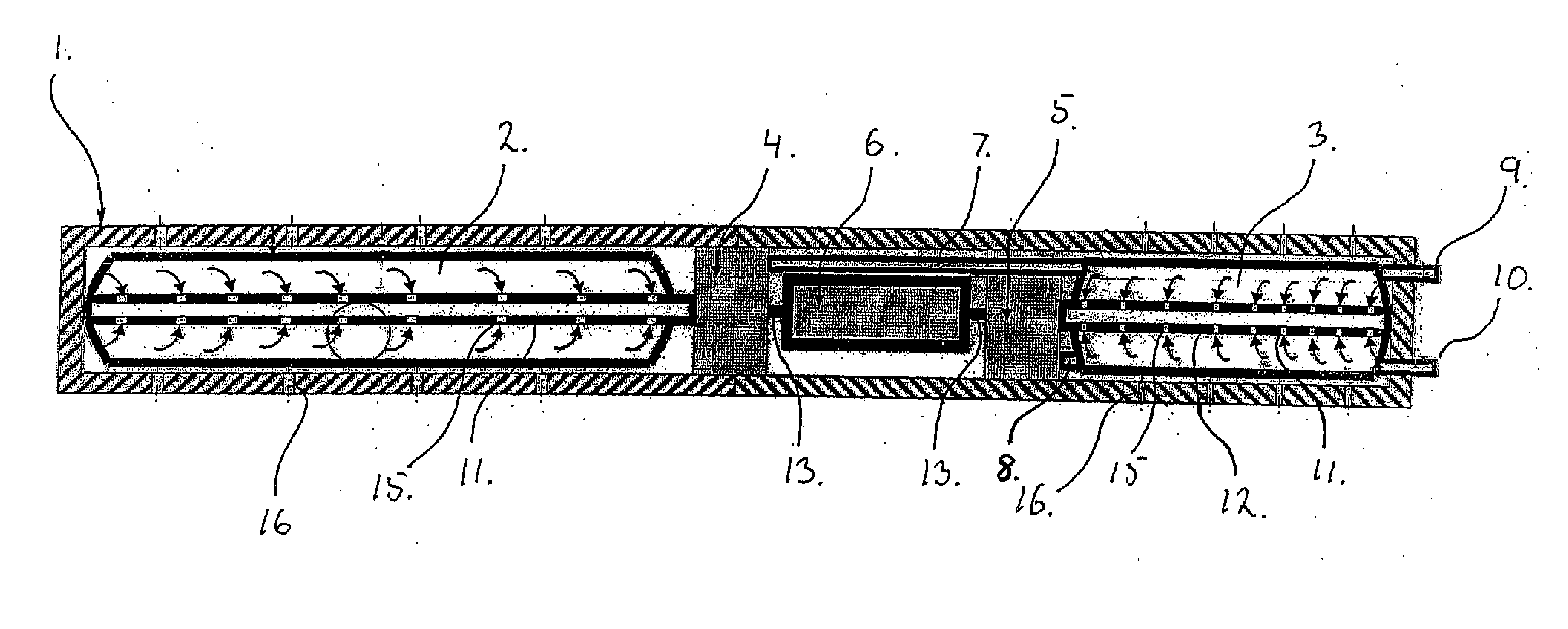
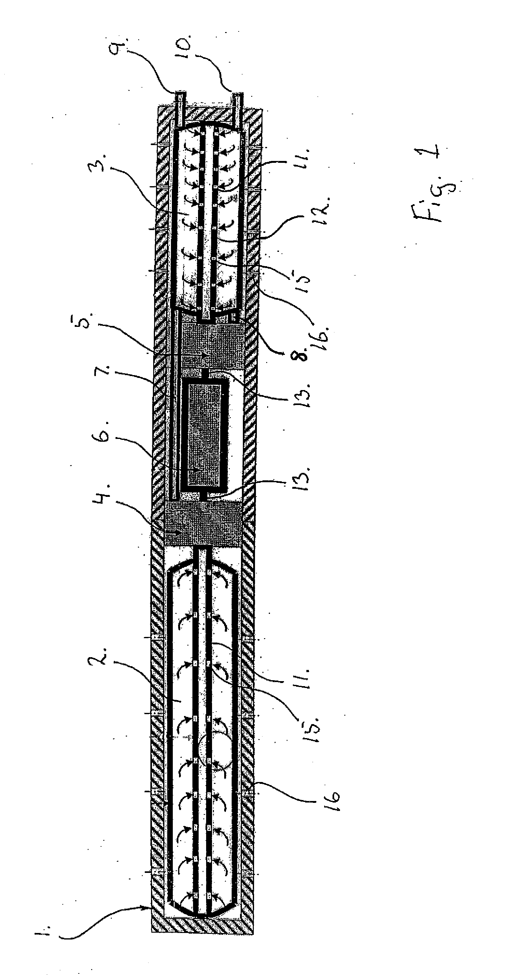
[0026]The injection system according to FIG. 1 comprises a casing 1 having a cross section so that the complete casing 1 can be lowered into a wellbore, or an inner lining in a wellbore (not shown). Normally the cross section of the casing 1 would be cylindrical, but other cross sections may be used within the scope of the invention. In the casing are arranged two cartridges 2 and 3, each containing fluid to be injected into the wellbore or inner lining in the wellbore.

[0027]The casing 1 also contains two pumps 4, 5 being connected respectively to the cartridges 1, 3 via the pipes 11, 12 extending from inside each cartridge 2, 3 respectively and to the inlet of each pump 4, 5. From each pump 4, 5 is arranged an outlet pipe 7, 8 respectively extending along the inside of the casing 1 an past the cartridge 3 and further through the casing 1 where the pipes 7, 8 end outside the casing 1 defining fluid outlets 9, 10 for injecting fluids to the wellbore or the inner lining in a wellbore....


PUM


Abstract

Method and apparatus for downhole injecting one or more treatment fluids, and especially for providing one or more seals in an annular space between a well tubular and the surrounding formation or between pipes of a wellbore system, said method comprising the steps of loading the or each treatment fluid separately into one or more fluid containers (2,3) arranged in a injection tool (1), each container comprising container walls surrounding the fluid in the fluid container, and an outlet opening, lowering the injection tool body into the wellbore or the well tubular to a predetermined position, pumping the fluids from each fluid container into the wellbore or the well tubular.

Description

FIELD OF THE INVENTION[0001]The present invention relates to the field of oil recovery from a wellbore.BACKGROUND OF THE INVENTION[0002]For oil recovery a well is drilled and a well tubular such as a casing or a liner is introduced into the well. The outside diameter of the well tubular is smaller than the inside diameter of the wellbore, thereby forming an annular space between the well tubular and the wellbore. The well tubular is perforated at one or more zones in order to facilitate the flow of hydrocarbons into the tubular and subsequent flow upstream for recovery. Occasionally contaminating materials such as water and sand are produced along with the hydrocarbons from a part of the subterranean formations surrounding the well tubular. In these situations it is desirable to seal off the well tubular from one or more parts of the annular space. Also in other situation it may be desirable to seal off the annular space.[0003]To seal off a desired part of, e.g., a well one possibil...

Claims


Application Information

Patent Timeline
IPC IPC(8): E21B43/00
CPCE21B27/02E21B43/26E21B33/1208
Inventor HEIJNEN, WILHELMUS HUBERTUS PAULUS MARIA
Owner TOTAL E&P DANMARK AS
Why Eureka
Try Eureka