Oil state monitoring method and oil state monitoring device

a monitoring method and oil state technology, applied in the direction of measurement devices, scientific instruments, instruments, etc., can solve the problems of gas turbine inoperable state, method (configuration) not fully satisfying the needs of oil users, and cannot identify what type of contaminants, etc., to limit errors in detecting color components.

Inactive Publication Date: 2012-04-12
UNIVERSITY OF FUKUI
View PDF11 Cites 26 Cited by
  • Summary
  • Abstract
  • Description
  • Claims
  • Application Information

AI Technical Summary

Benefits of technology

[0016]A product of oil is composed of base oil and additive agents. Using oil for machinery for a long term increases contaminants in the oil, and not only causes a negative impact on lubricity and operability of the machinery but also raises a possibility of losing properties given to the oil through consumption of additive agents in the oil. Consequently, purification of the oil which has lost its own properties such as antioxidant capabilities for attempting to use it for a long term will possibly not bring the expected results. Antioxidant capabilities of oil include a capability intrinsically owned by the base oil and a capability given by the additive agents. For example, while additive agents in oil, which are highly reactive substances, are sacrificing themselves and protecting the oil from changing the properties due to oxidation, refilling new oil for the consumed additive agents prevents damage from reaching base oil itself in the oil and can extend use duration of the oil.
[0018]The aim of the present invention is to provide a method and a device for monitoring oil states which are capable of monitoring oil states with high accuracy in order to properly estimate life expectancy of oil used in various machinery or equipment.
[0021]Then, such aspect of the present invention can monitor oil degradation states according to the contaminants captured in the filter and provide the oil state monitoring method which makes it possible to monitor oil states with high accuracy in order to properly estimate life expectancy of oil used for various machinery or equipment.
[0027]Then, such aspect of the present invention can monitor oil degradation states according to the contaminants captured in the filter and provide the oil state monitoring device which makes it possible to monitor oil states with high accuracy in order to properly estimate life expectancy of oil used for various machinery or equipment.
[0032]Moreover, the aforementioned oil state monitoring device may have the first light source and the first color sensor installed not facing each other in the oil state monitoring device. Such positional relation can limit errors in detecting the color components due to distribution of intensity of the first transmitted light.

Problems solved by technology

In addition, ASTM D4898 and JIS B9931, which are previously described as a method for measuring contaminated object-weight in oil, measure total weight of contaminants in oil (100 cc), but cannot identify what type of contaminants are included in oil.
In addition, even if the voltammetric method judges that sufficient amount of additive agents remain in oil, antioxidant products generated in the oil put gas turbines inoperative states in many cases.
Therefore, the aforementioned conventional methods (configurations) do not satisfy such needs of users of oil fully.
Using oil for machinery for a long term increases contaminants in the oil, and not only causes a negative impact on lubricity and operability of the machinery but also raises a possibility of losing properties given to the oil through consumption of additive agents in the oil.
Consequently, purification of the oil which has lost its own properties such as antioxidant capabilities for attempting to use it for a long term will possibly not bring the expected results.

Method used


Image

  • Oil state monitoring method and oil state monitoring device
  • Oil state monitoring method and oil state monitoring device
  • Oil state monitoring method and oil state monitoring device

Examples


Embodiment Construction

[0048]Details of embodiments for carrying out the present invention are explained with the figures. The present invention is not limited to the following described configurations, and may use various configurations under the same technological idea. For example, a certain unit can be omitted from the following described-each configuration.

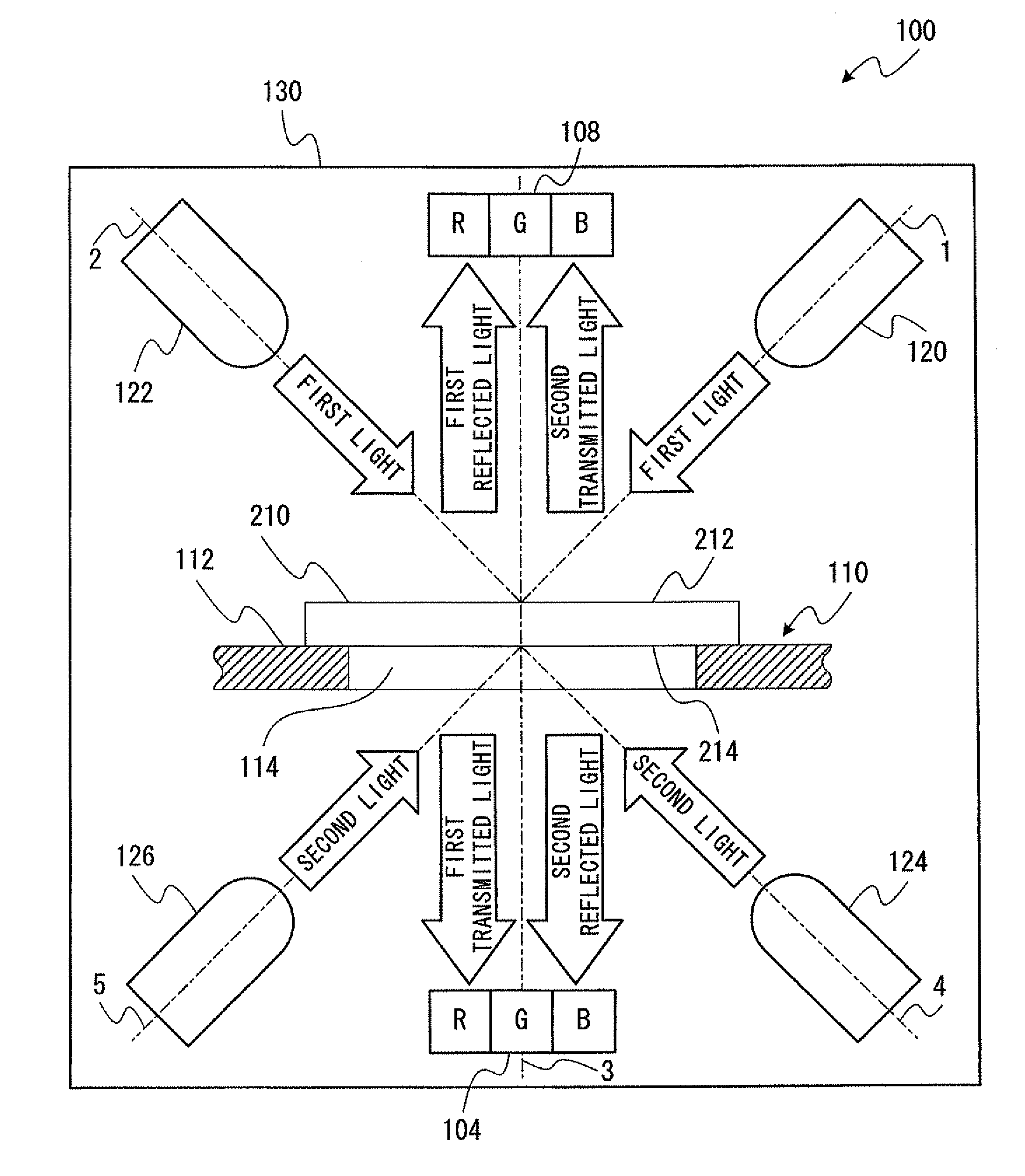
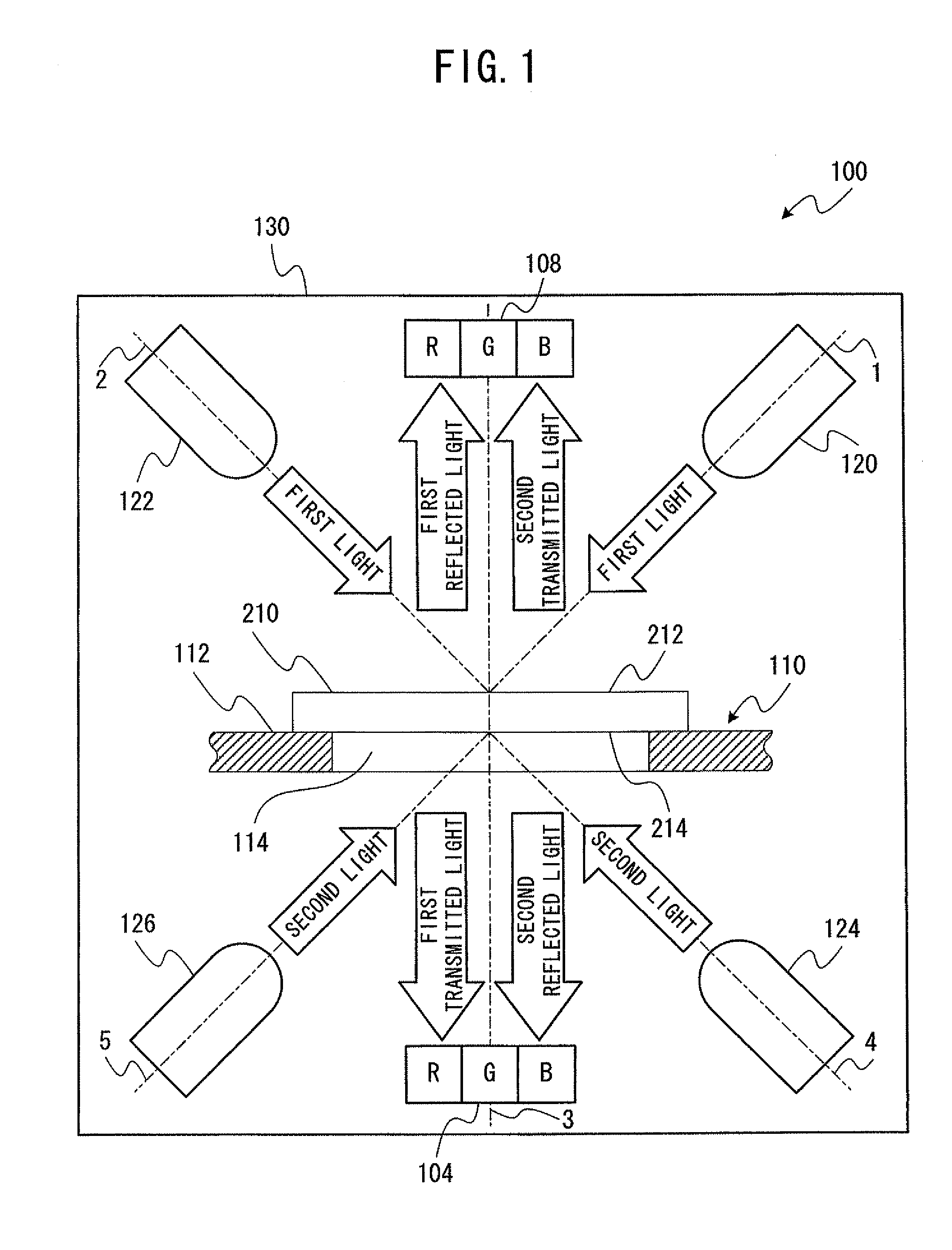
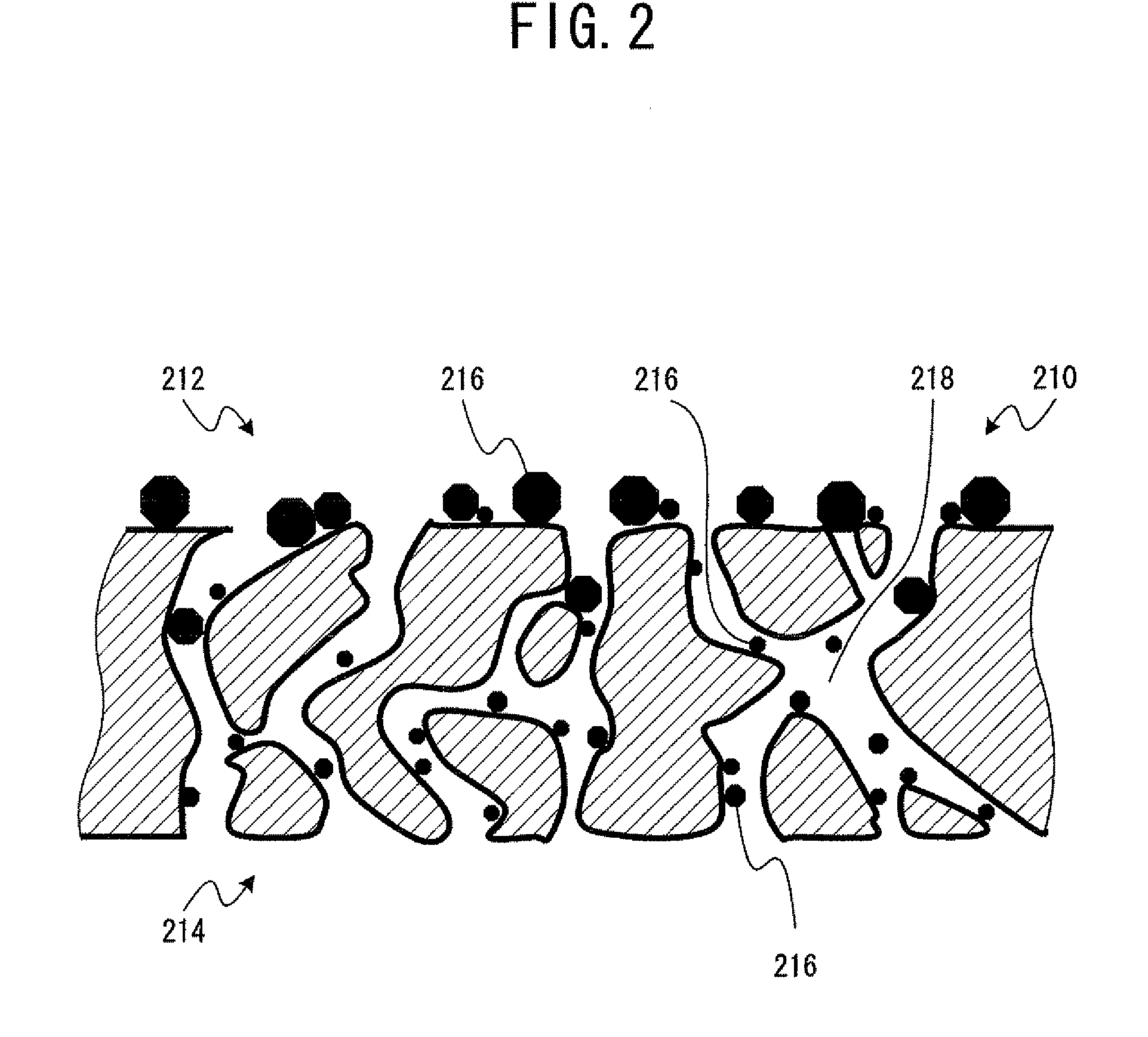
[0049](Oil state monitoring device) An oil state monitoring device 100 is explained with FIG. 1. The oil state monitoring device 100 is a device for monitoring oil degradation states. Oil degradation states are monitored with a membrane filter 210 which filters oil used for machinery or equipment as shown in FIG. 6, and which captures contaminants 216 which are present in the oil prior to an oil filtration as shown in FIG. 2.

[0050]The oil state monitoring device 100 includes first light sources 120, 122, and a first color sensor 104. In addition, the oil state monitoring device 100 includes second light sources 124, 126, and a second color sensor 1...


PUM

PropertyMeasurementUnit
wavelengthsaaaaaaaaaa

Abstract

Disclosed are an oil state monitoring method and an oil state monitoring device which monitor the state of degradation of oil used in machinery or equipment. In monitoring the oil state by the oil state monitoring method and by the oil state monitoring device, oil used in machinery or equipment is filtered when the degradation state of the aforementioned oil is to be monitored. By means of filtration, the oil content is removed from the filter which captured contaminants that were present in oil prior to filtration. Light is projected onto the filter from which oil was removed. The projected light detects the color components of the transmitted light which penetrated the aforementioned filter.

Description

FIELD OF THE INVENTION[0001]This invention pertains to an oil state monitoring method and an oil state monitoring device.BACKGROUND OF THE INVENTION[0002]Oil such as lubricant oil, hydraulic fluid, turbine oil and the like is used for various machinery or equipment. Degradation of oil causes breakdowns of or troubles with machinery and the like. Concretely, oil comes to the end of its life when oil-degradation-states reach a certain level, and using machinery and the like with such dead oil as it is will raise possibility of causing troubles with the machinery and the like. Therefore, monitoring oil degradation states is a key for preventing the troubles from occurring. Specifications related to such monitoring have been established and various technologies related to such monitoring have been proposed.[0003]ASTM D1500 is known as one of conventional test methods for estimating life expectancy of oil by colors of oil itself. The method uses one of oil characteristics that colors of ...

Claims


Application Information

Patent Timeline
Patent Type & Authority Applications(United States)
IPC IPC(8): G01N21/59
CPCG01N21/27G01N2015/0283G01N33/2888G01N21/31
Inventor HONDA, TOMOMIIWAI, YOSHIROSASAKI, AKIRA
Owner UNIVERSITY OF FUKUI
Why Eureka
Try Eureka