
Rotor For Turbomachines With Shrouded Blades

Active Publication Date: 2012-04-12
GE AVIO
View PDF1 Cites 6 Cited by
  • Summary
  • Abstract
  • Description
  • Claims
  • Application Information

AI Technical Summary

Benefits of technology

[0003]The object of the present invention is to provide a rotor for a turbomachine with shrouded blades, which reduces or eliminates the vibrations and the associated inconveniences described above.

Problems solved by technology

It is known that, in use, the blades of a rotor of this type are subject to vibratory motion generated both by the impulsive forces applied thereto, and by any unbalance of the blade row, and that the vibrations of the blades can be sufficient to cause repeated collisions or scraping of each sector of the external ring with the adjacent sectors and that the scraping can relatively quickly cause said external ring to become worn.

Method used


Image

  • Rotor For Turbomachines With Shrouded Blades
  • Rotor For Turbomachines With Shrouded Blades
  • Rotor For Turbomachines With Shrouded Blades

Examples


Embodiment Construction

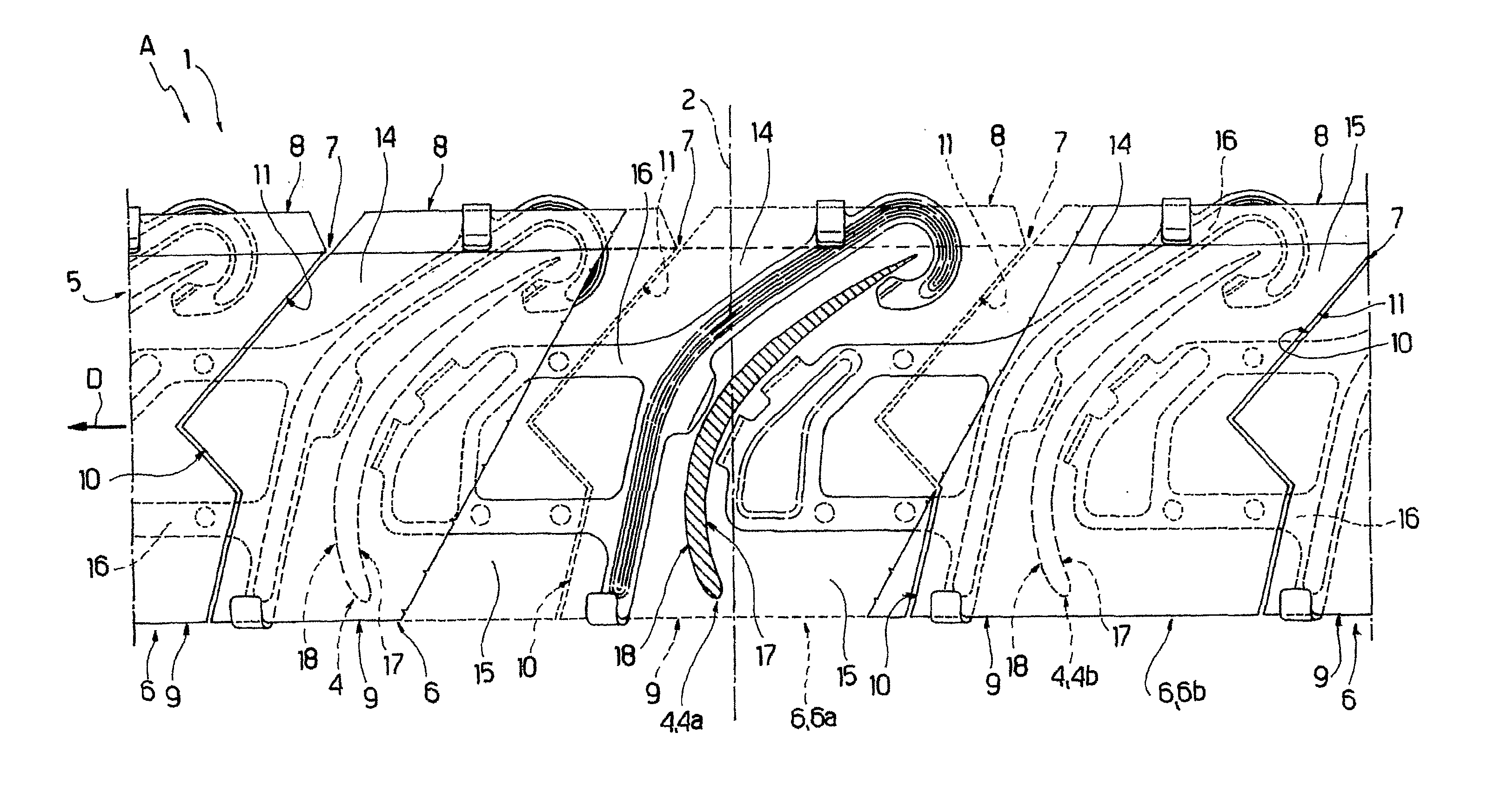
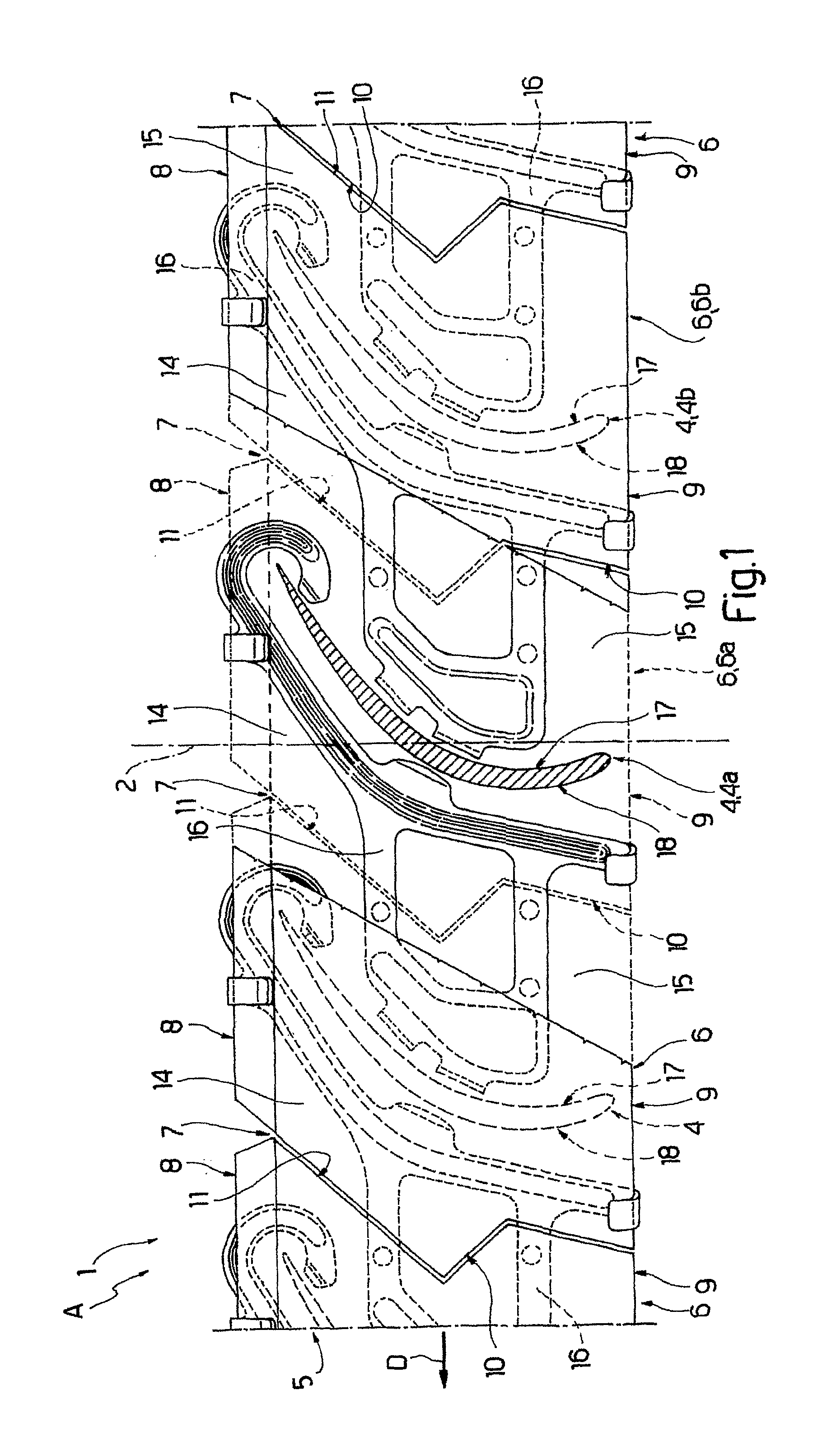
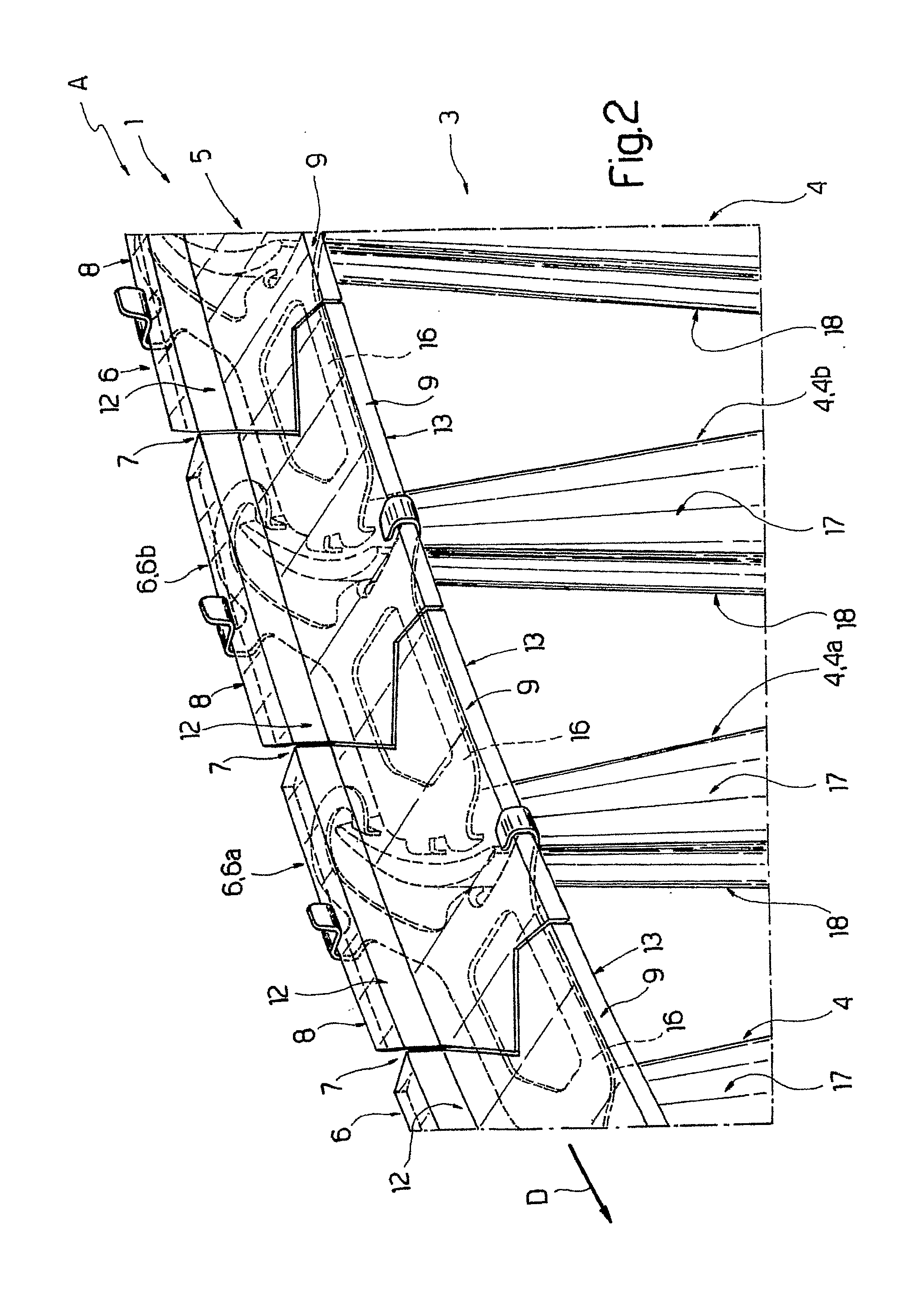
[0010]In FIGS. 1 and 2, designated as a whole by number 1 is a rotor of a turbomachine A. The rotor 1 is mounted so as to rotate about an axis 2 in a direction D and comprises at least one row 3 of blades 4 coaxial to the axis 2; and at least one external ring 5, which covers the row 3 and is coaxial to the axis 2. The external ring 5 consists of a plurality of sectors 6, commonly referred to as shrouds, each of which is separated from each of the adjacent sectors 6 by means of a relative air gap 7 and is fixed to the free end of a respective blade 4.

[0011]Each sector 6 is defined by a substantially flat plate, the lateral edges of which are defined by two flat circumferential surfaces 8 and 9 that are substantially in a same plane and parallel to one another, and by a generally convex front transverse surface 10 (in relation to the direction D) and by a generally concave rear transverse surface 11 that are complementary with respect to one another. In particular, the front transver...


PUM


Abstract

A rotor for turbomachines with shrouded blades comprising a row of a plurality of blades covered by an external ring, coaxial to said row of blades; the external ring being composed of a plurality of sectors, commonly referred to as shrouds, which are adjacent to one another and transversely and circumferentially attached to the end of respective blades; a damping member being arranged so as to straddle a respective pair of adjacent sectors and being pushed, in use, against radially internal surfaces of the sectors of the pair of adjacent sectors.

Description

TECHNICAL FIELD[0001]The present invention relates to a rotor for turbomachines with shrouded blades, said rotor being of the type comprising a blade row and an external ring comprising a plurality of sectors, commonly referred to as shrouds, each of which is fixed to the free end of a respective blade and is separated from each adjacent sector by an air gap.BACKGROUND ART[0002]It is known that, in use, the blades of a rotor of this type are subject to vibratory motion generated both by the impulsive forces applied thereto, and by any unbalance of the blade row, and that the vibrations of the blades can be sufficient to cause repeated collisions or scraping of each sector of the external ring with the adjacent sectors and that the scraping can relatively quickly cause said external ring to become worn.DISCLOSURE OF INVENTION[0003]The object of the present invention is to provide a rotor for a turbomachine with shrouded blades, which reduces or eliminates the vibrations and the assoc...

Claims


Application Information

Patent Timeline
IPC IPC(8): F01D5/26
CPCF05D2260/96F01D5/225
Inventor CALZA, PAOLOGRILLO, ROSARIOSALVANO, SERGIO
Owner GE AVIO
Learn More