
Parameter-sensing endotracheal tube

a technology of trachea and parameter sensing, applied in the field of endotracheal tubes, can solve the problems of serious throat injury, brain injury, and difficulty in trachea detection,

Inactive Publication Date: 2012-04-12
SCHLAGER DAN
View PDF12 Cites 7 Cited by
  • Summary
  • Abstract
  • Description
  • Claims
  • Application Information

AI Technical Summary

Benefits of technology

[0014]These needs, and others that will become apparent, are met by specific embodiments of an endotracheal tube that include at least one of the following elements: an ultrasound-observable flexible body, a heating member for warming inhalation gases, a sensor for measuring pressure b

Problems solved by technology

The method is not without its difficulties, and there is a risk of serious injury to the throat, and in some cases of prolonged interruption of breathing, injury to the brain, and even death resulting from lack of oxygen.
These risks are particularly pronounced in emergency situations.
The intubating stylete has drawbacks, as do all the devices of this class, one of which is that its presence in the tube's airway prevents the attachment of a hand operated bag valve or of a mechanical ventilator during the intubation procedure.
As a result, use of a stylete risks a delayed airflow to the lungs during the critical intubation process, causing some health care professionals to avoid use of the intubating stylete and the other guidance devices of a similar nature.
Another drawback is that the metal used to form a typical wire stylete is not sufficiently ultrasound reflective to make the wire easily observable within the patient; a point not made in the '586 patent.
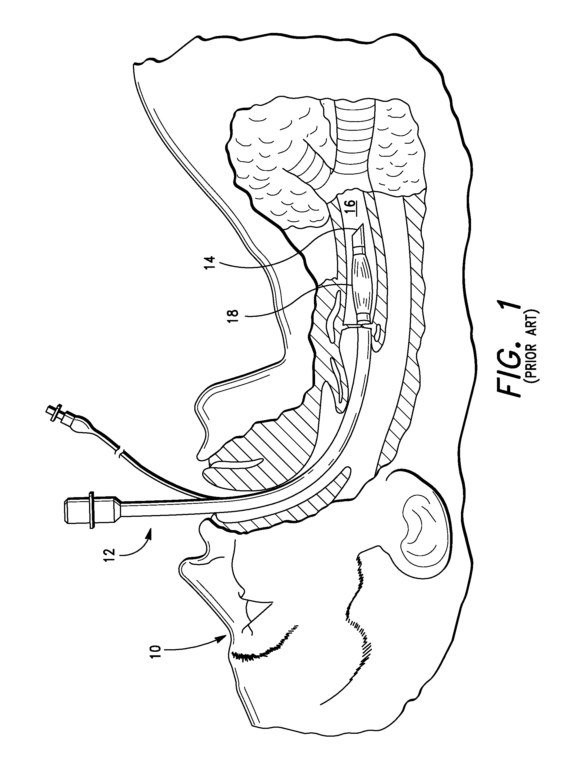
The flexible plastic body of a typical endotracheal tube, of which FIG. 1 is a representative example, is also not easily observable within the patient using ultrasound for assistance during intubation.
What is needed is an ultrasound reflective plastic body that makes the tube readily observable by the health care professional during a tracheal intubation to insure the tube enters the trachea (windpipe), and not the esophagus (carries food and water to the stomach), an error all too common with existing methods.
For endotracheal tubes equipped with an inflatable cuff near the distal end for sealing the trachea once intubation is achieved, there is always a danger that over inflation of the cuff may cause injury to the patient, while under inflation can result in regurgitated stomach content being forced into the lungs.
Such accidents are especially prone to occur in emergency situations and during patient transport, such as in an ambulance or helicopter.
Finally, no known endotracheal tube includes a sensor for measuring CO2 concentration of exhaled gases.

Method used


Image

  • Parameter-sensing endotracheal tube
  • Parameter-sensing endotracheal tube
  • Parameter-sensing endotracheal tube

Examples


Embodiment Construction

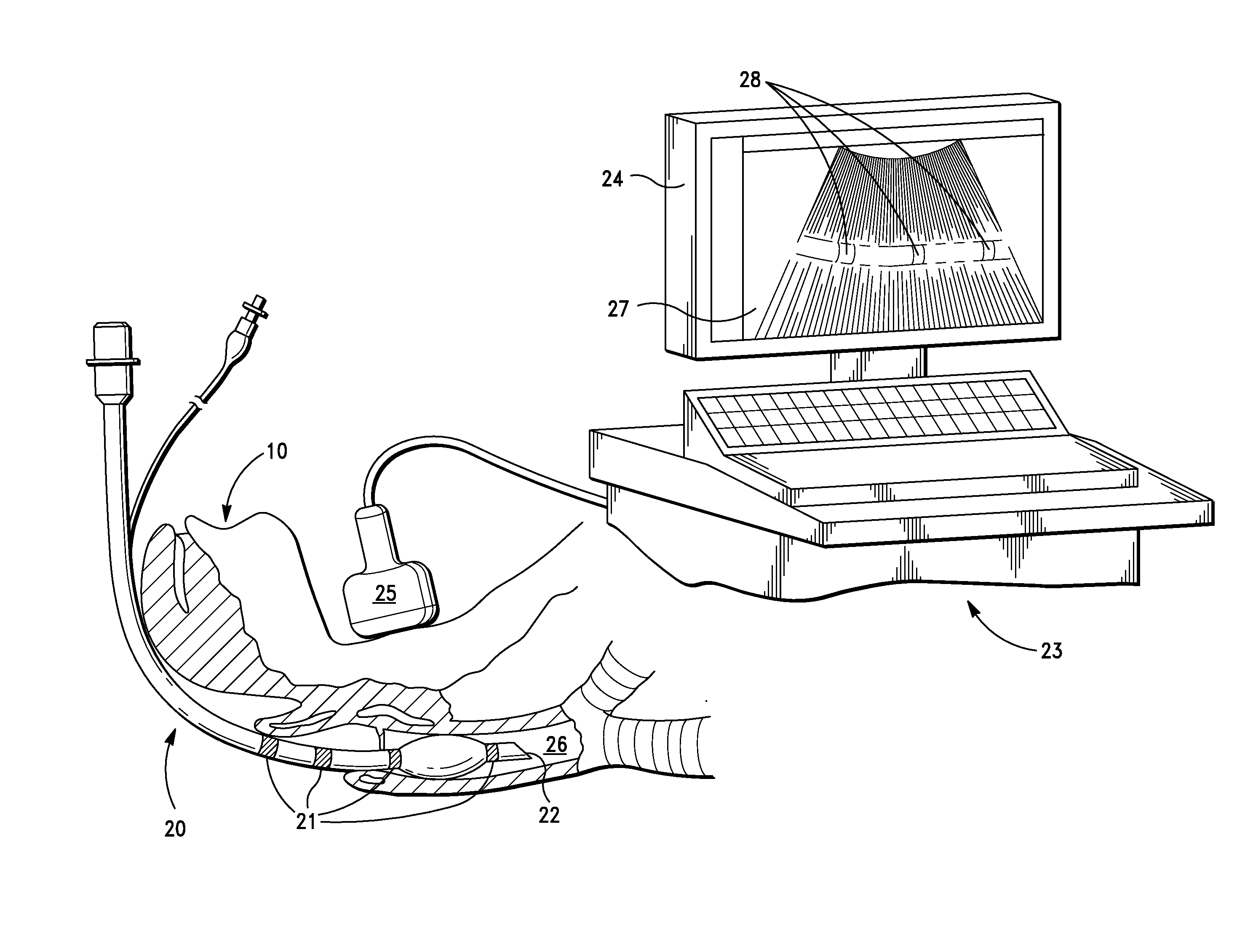
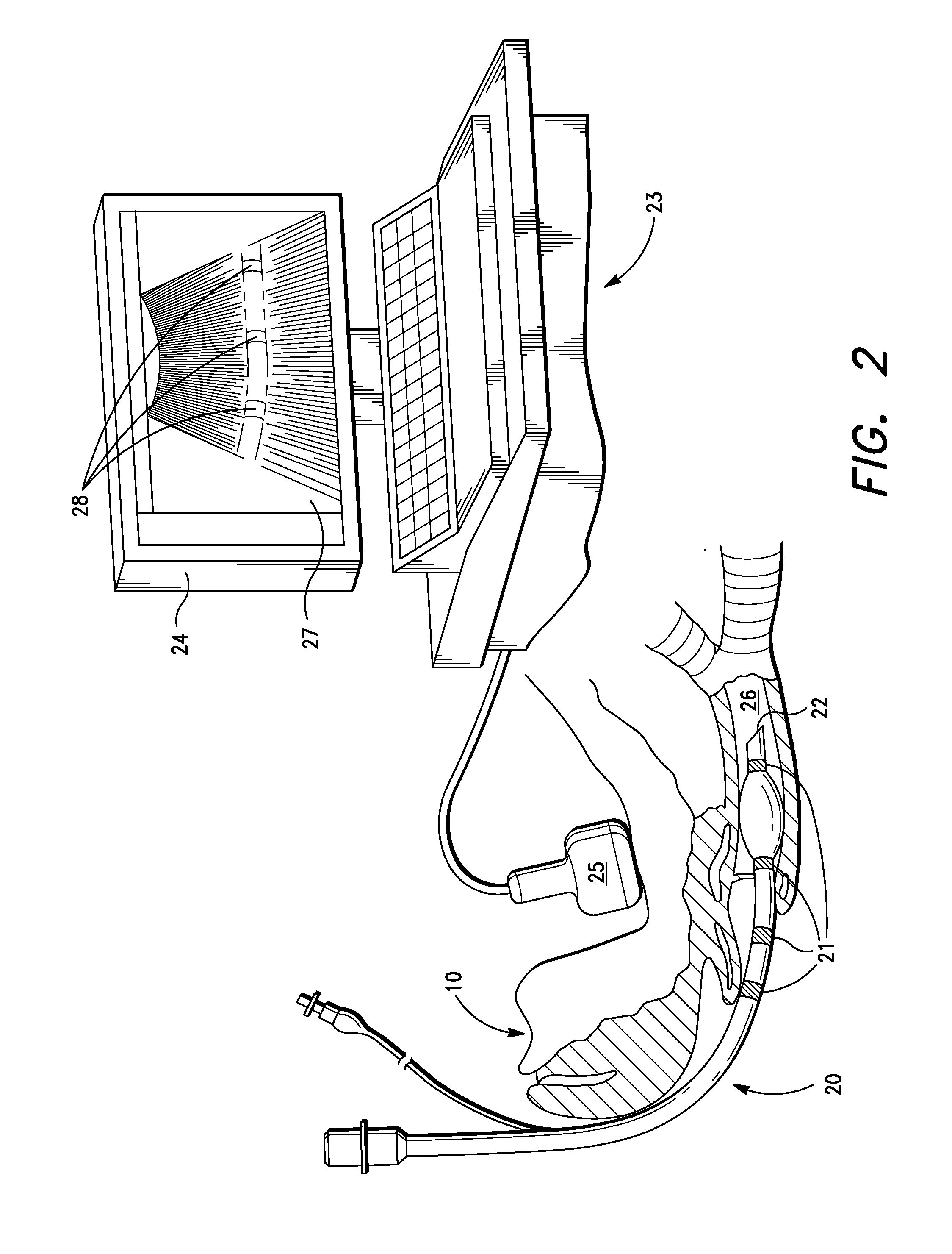
[0025]With reference to FIG. 2 there is shown a partial pictorial diagram illustrating a portion of the patient 10 of the prior art FIG. 1, and the use of an ultrasound observable endotracheal tube 20 according to a specific embodiment of the present invention. The patient 10 is intubated with the endotracheal tube 20 having ultrasound-reflecting elements 21 disposed near a distal end 22. Also shown is an ultrasound machine 23 including a display 24 and a hand-held ultrasound wand 25. The endotracheal tube 20 has been properly inserted into the patient's trachea 26 with the aid of ultrasound for observing the location of the tube within the patient's throat. An ultrasound image 27 includes a portion of the endotracheal tube 20 including stripes 28, corresponding to the ultrasound-reflecting elements 21.

[0026]The hand held ultrasound wand 25 is located approximately above the patient's laryngeal prominence (Adam's apple). Experience teaches that this region is a likely place to view ...


PUM


Abstract

A sensor-equipped endotracheal tube has a flexible body surrounding an airway lumen and includes sensors for monitoring physiological parameters such as CO2 / O2 concentration in respiratory gases, and patient body temperature. These sensors provide electrical output for parameter display on suitable ventilators and monitors. In another specific embodiment, the endotracheal tube includes a sensor for measuring pressure exerted between an inflation cuff and a patient's tracheal tissues for preventing injury from over / under cuff inflation. Other specific embodiments of the sensor equipped endotracheal tube include combining sensors with a heating member for warming inhaled respiratory gases, and with ultrasound reflecting elements that make the tube visible within the body using ultrasound.

Description

RELATED APPLICATION AND CLAIM OF PRIORITY[0001]This non-provisional U.S. patent application is a continuation-in-part of co-pending U.S. patent application Ser. No. 12 / 901,491 filed 2010 Oct. 9 entitled ULTRASOUND-OBSERVABLE, RESPIRATORY GAS-WARMING, PARAMETER-SENSING ENDOTRACHEAL TUBE. This patent application claims priority from the filing date of said co-pending patent application pursuant to the provisions of 35 U.S.C. §120.[0002]New matter introduced in this continuation-in-part is found at the BRIEF DESCRIPTION OF THE DRAWING section and includes new drawing FIGS. 9a, 9b and 10. Additional new matter continues at the end of the original DESCRIPTION OF THE PREFERRED EMBODIMENT section following the description of original FIG. 8c. FIELD OF THE INVENTION[0003]The invention relates generally to endotracheal tubes, and more particularly, to tubes including elements, singly and in combination, for improving ultrasound observability, for the warming of inhaled gases, and for the mea...

Claims


Application Information

Patent Timeline
IPC IPC(8): A61B8/12A61B5/087A61B5/08
CPCA61B5/083A61B8/0841A61B8/486A61M16/04A61M2016/0413A61M2205/32A61M16/1095A61M2205/3368A61M2230/432A61M2230/435A61M2230/50A61M16/0418A61M2205/332A61M16/0486
Inventor SCHLAGER, DANBUCKLEY, JR., DELMAS R.
Owner SCHLAGER DAN
Learn More