Mechanical compaction of insulator for insulated conductor splices

a technology of mechanical compaction and insulator, which is applied in the direction of insulation, drilling pipes, and wellbore/well accessories, etc., can solve the problems of electrical insulators to overcome, electrical insulators to splice together, and core bulge or other mechanical defects to occur

Active Publication Date: 2012-04-19
SALAMANDER IP HLDG LLC
View PDF11 Cites 26 Cited by
  • Summary
  • Abstract
  • Description
  • Claims
  • Application Information

AI Technical Summary

Problems solved by technology

There are many potential problems during manufacture and / or assembly of long length insulated conductors.
For example, there are potential electrical and / or mechanical problems due to degradation over time of the electrical insulator used in the insulated conductor.
There are also potential problems with electrical insulators to overcome during assembly of the insulated conductor heater.
Problems such as core bulge or other mechanical defects may occur during assembly of the insulated conductor heater.
Such occurrences may lead to electrical problems during use of the heater and may potentially render the heater inoperable for its intended purpose.
Conventional MI cable splice designs are typically not suitable for voltages above 1000 volts, above 1500 volts, or above 2000 volts and may not operate for extended periods without failure at elevated temperatures, such as over 650° C.
Such methods do not provide sufficient compaction of the mineral insulation or even allow any compaction of the mineral insulation, and are not suitable for making splices for use at the high voltages needed for these subsurface applications.
In addition, there may be problems with increased stress on the insulated conductors during assembly and / or installation into the subsurface of the insulated conductors.
For example, winding and unwinding of the insulated conductors on spools used for transport and installation of the insulated conductors may lead to mechanical stress on the electrical insulators and / or other components in the insulated conductors.

Method used


Image

  • Mechanical compaction of insulator for insulated conductor splices
  • Mechanical compaction of insulator for insulated conductor splices
  • Mechanical compaction of insulator for insulated conductor splices

Examples


examples

[0267]Non-restrictive examples are set forth below.

Samples Using Fitting Embodiment Depicted in FIG. 5

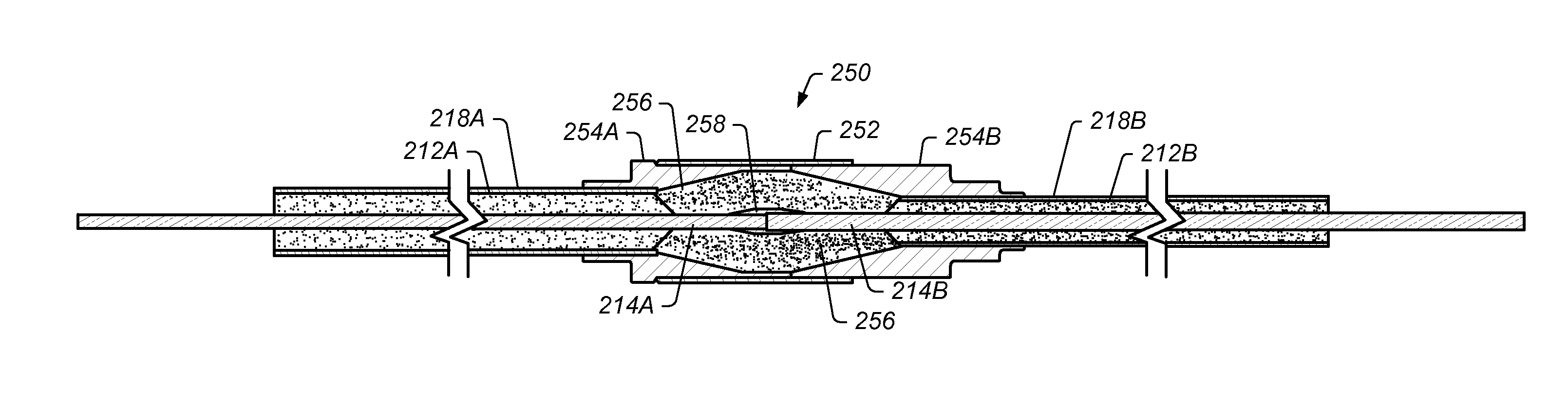
[0268]Samples using an embodiment of fitting 250 similar to the embodiment depicted in FIG. 5 were fabricated using a hydraulic compaction machine with a medium voltage insulated conductor suitable for use as a subsurface heater on one side of the fitting and a medium voltage insulated conductor suitable for use as an overburden cable on the other side of the fitting. Magnesium oxide was used as the electrically insulating material in the fittings. The samples were 6 feet long from the end of one mineral insulated conductor to the other. Prior to electrical testing, the samples were placed in a 6½ ft long oven and dried at 850° F. for 30 hours. Upon cooling to 150° F., the ends of the mineral insulated conductors were sealed using epoxy. The samples were then placed in an oven 3 feet long to heat up the samples and voltage was applied to the samples using a 5 kV (max) hipot (high po...


PUM

PropertyMeasurementUnit
temperaturesaaaaaaaaaa
voltagesaaaaaaaaaa
voltagesaaaaaaaaaa

Abstract

A method for coupling ends of two insulated conductors includes coupling an end portion of a core of a first insulated conductor to an end portion of a core of a second insulated conductor. At least a part of the end portions of the cores are at least partially exposed. Electrically insulating material is placed over the exposed portions of the cores. A sleeve is placed over end portions of the two insulated conductors to be coupled. The sleeve includes one or more raised portions. The end portions include the exposed portions of the cores. The sleeve is coupled to jackets of the insulated conductors. The raised portions of the sleeve are mechanically compressed until the raised portions of the sleeve have a diameter substantially similar to a remainder of the sleeve. The compression of the raised portions of the sleeve compacts the electrically insulating material inside the sleeve.

Description

PRIORITY CLAIM[0001]This patent application claims priority to U.S. Provisional Patent Application Ser. No. 61 / 391,399 entitled “SYSTEMS AND METHODS FOR JOINING INSULATED CONDUCTORS” to Coles et al. filed on Oct. 8, 2010; and U.S. Provisional Patent No. 61 / 473,594 entitled “SYSTEMS AND METHODS FOR JOINING INSULATED CONDUCTORS” to Coles et al. filed on Apr. 8, 2011, all of which are incorporated by reference in their entirety.RELATED PATENTS[0002]This patent application incorporates by reference in its entirety each of U.S. Pat. Nos. 6,688,387 to Wellington et al.; 6,991,036 to Sumnu-Dindoruk et al.; 6,698,515 to Karanikas et al.; 6,880,633 to Wellington et al.; 6,782,947 to de Rouffignac et al.; 6,991,045 to Vinegar et al.; 7,073,578 to Vinegar et al.; 7,121,342 to Vinegar et al.; 7,320,364 to Fairbanks; 7,527,094 to McKinzie et al.; 7,584,789 to Mo et al.; 7,533,719 to Hinson et al.; 7,562,707 to Miller; and 7,798,220 to Vinegar et al.; U.S. Patent Application Publication Nos. 2009...

Claims


Application Information

Patent Timeline
Patent Type & Authority Applications(United States)
IPC IPC(8): H01R43/04
CPCE21B17/003Y10T29/49197H01R4/70H01R13/41H02G1/14Y10T29/49172H01R4/00H01R43/00Y10T29/49199Y10T29/49176Y10T29/49195Y10T29/49171Y10T29/49208Y10T29/49194Y10T29/49117E21B36/04E21B19/24H02G15/046
Inventor HARMASON, PATRICK SILASD'ANGELO, III, CHARLES
Owner SALAMANDER IP HLDG LLC
Why Eureka
Try Eureka