Water heater and control method therefor

a control method and water heater technology, applied in the field of water heaters, can solve the problems of complicated structure and complicated disposition of water heaters, and achieve the effect of simple control structur

Active Publication Date: 2012-04-19
PURPOSE CO LTD
View PDF43 Cites 37 Cited by
  • Summary
  • Abstract
  • Description
  • Claims
  • Application Information

AI Technical Summary

Benefits of technology

[0012]An object of the present invention relates to a water heater in which hot water is circulated in a circulation line to be supplied, and is to achieve a simple control structure.

Problems solved by technology

This disposition complicates the structure of a water heater.
There is a problem that the structure of a water heater is complicated because individual control means is provided for a planned circulation process.

Method used


Image

  • Water heater and control method therefor
  • Water heater and control method therefor
  • Water heater and control method therefor

Examples


first embodiment

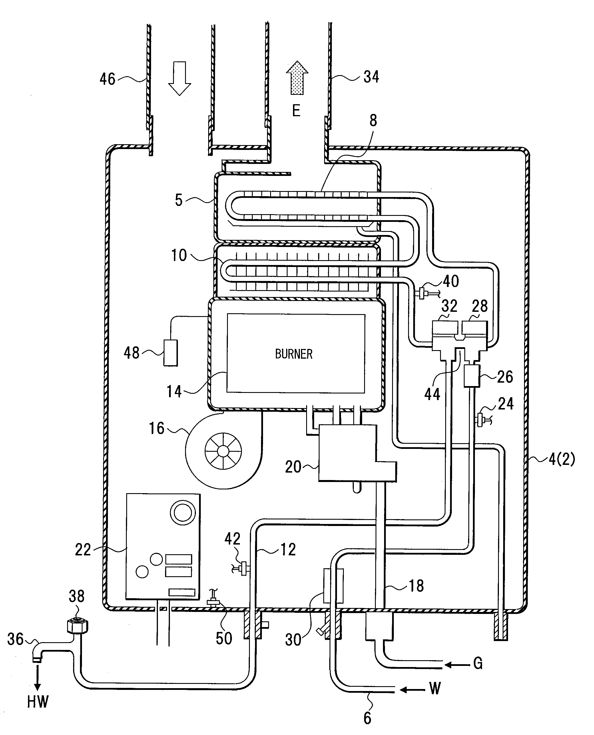
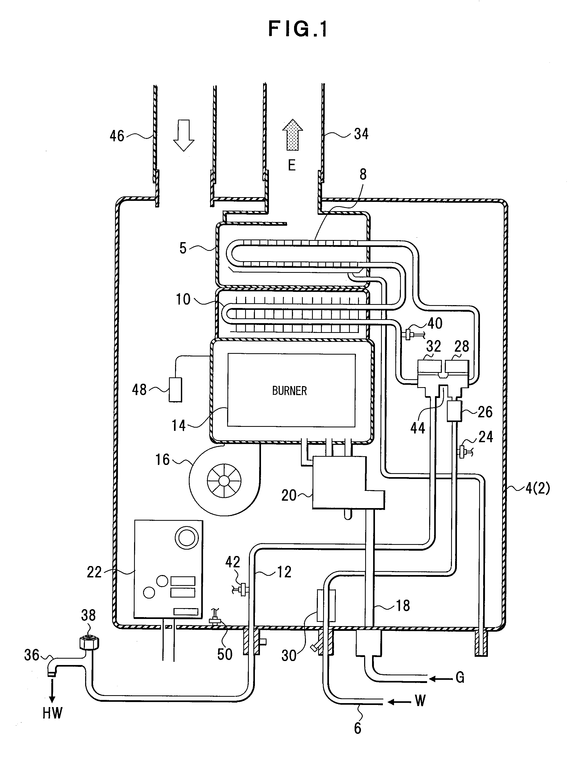
[0044]A first embodiment will be described with reference to FIGS. 1 to 4. FIG. 1 depicts an example of structure of a heat pump in a water heater according to the first embodiment, FIG. 2 depicts an example of structure of the water heater, FIG. 3 depicts an example of connection between a circulation pump and a control unit, and FIG. 4 depicts an example of structure of a bypass pipe. Each structure depicted in FIGS. 1 to 4 is an example, and thus the present invention is not limited to such a structure.

[0045]This combustion device 4 is an example of a heat pump of a water heater 2 of the present invention, and is means for heating, for example, tap water W, which is supplied from an inlet of the combustion device 4, by exchanging its heat for exhaust E, which is generated by combustion of fuel gas G etc., and supplying hot water HW. The combustion device 4 includes, as depicted in FIG. 1, a water supply pipe 6 that introduces the tap water W into the combustion device 4, a second...

second embodiment

[0079]A second embodiment represents an example of structure of a water heater in which a plurality of combustion devices are disposed.

[0080]The second embodiment will be described with reference to FIG. 5. FIG. 5 depicts an example of structure of a water heater according to the second embodiment. The structure depicted in FIG. 5 is an example, and the present invention is not limited to such a structure. In FIG. 5, the same components as those in FIGS. 1 and 2 are denoted by the same reference numerals.

[0081]This water heater 100 is an example of a water heater of the present invention. In the water heater 100, for example, a plurality of equivalent combustion devices 4A to 4D are disposed in parallel. The devices use water supply pipe 6 and hot water outgoing pipe 12 commonly to supply hot water HW to a hot water supply part. In the water heater 100, as described above, the combustion devices 4A to 4D, the water supply pipe 6 and the hot water outgoing pipe 12 cycles via a circul...

examples

[0137]An example of a water heater will be described with reference to FIG. 13. FIG. 13 depicts an example of a water heater.

[0138]In this water heater 100, the tap water pipe 64 are joined to the circulation line 62, and the tap water W of lower temperature and the return water RW of higher temperature are supplied to the combustion device 4. A Y shaped strainer 130 is provided in the tap water pipe 64 as an example of water straining means. An expansion tank 132 storing the tap water W and the return water RW may be provided in the water supply pipe 6. An air vent 134 is provided for discharging the air in the heated hot water HW for the hot water supply part on the hot water outgoing pipe 12.

[0139]An air separator 136 is disposed in front of the circulation pump 70 on the circulation line 62.

[0140]Features and advantages of the water heater and control method therefor of the present invention described above are as follows.

[0141](1) In the present invention, the circulation pump ...


PUM

PropertyMeasurementUnit
temperatureaaaaaaaaaa

Abstract

A water heater includes one or a plurality of heat pumps that heat tap water or return water from a hot water supply part, a circulation line that supplies hot water heated in the heat pumps to the hot water supply part, and introduces the return water from the hot water supply part to the heat pumps, an incoming water pipe that joins to between the hot water supply part in the circulation line and the heat pumps and supplies the tap water, a circulation pump that returns the return water to the heat pumps and circulates the return water through the circulation line, and a control unit that controls operation or stop of the circulation pump according to driving operation time or elapsed stop time by linking a combustion process of the heat pumps.

Description

BACKGROUND OF THE INVENTION[0001]1. Field of the Invention[0002]The present invention relates to a water heater in which a circulation line is provided in a water heating part for circulating hot water, and in which operation of a heat pump and a circulation pump is controlled according to temperature of the circulated hot water, elapsed time, etc.[0003]2. Description of the Related Art[0004]Conventionally, there is a water heater in which a pump is individually disposed in a hot water supply pipe and hot water is circulated therein. Thus, hot water of desired temperature is available instantaneously. In a case of such circulation, the pump is turned ON / OFF by a switch including a temperature sensor so as to supply hot water at prescribed setting temperature, for example, the switch is provided with a thermostat or a timer.[0005]A controller for pump control is on the market. This controller detects temperature on a pipe or water temperature in the pipe by, for example, being attach...

Claims


Application Information

Patent Timeline
Patent Type & Authority Applications(United States)
IPC IPC(8): F25B27/00
CPCF25B27/00F24D17/0026F24D17/0078F24D17/02F24D19/1051F24D19/1054F24D2200/043F24D2200/12F24H8/00B01B1/00Y02B30/00F24D3/08F24H15/335F24H15/486F24H15/31F24H15/45F24H15/269F24H15/345F24H15/219F24H15/395F24H15/215F24H15/325F24H15/36F24H15/25F24H15/258F24H15/421F24H15/136F24H15/238F24H15/281F24H15/175
Inventor HATADA, YASUTAKANAKAGAWA, KAZUHIKONAITOH, KATUMI
Owner PURPOSE CO LTD
Why Eureka
Try Eureka