Acoustic and electric combined stringed instrument of violin group

a combined stringed instrument and electric technology, applied in the field of stringed instruments of violin groups, can solve the problems of difficult to obtain abundant harmonics, soundboards that fail to amplify faint sounds, and low volume of sound

Inactive Publication Date: 2012-04-19
J WONMUSIC
View PDF30 Cites 18 Cited by
  • Summary
  • Abstract
  • Description
  • Claims
  • Application Information

AI Technical Summary

Benefits of technology

[0009]Therefore, the present invention has been made in view of the above problems, and it is an object of the present invention to provide a stringed instrument of a violin group, which can not only produce original acoustic sound, but also realize electric amplification of sound signals while maintaining the original sound to the maximum extent possible, using a single musical instrument.

Problems solved by technology

Considering some installation examples of the piezoelectric element, firstly, if the piezoelectric element is installed immediately below the bridge in the same manner as in an electric violin, the piezoelectric element may vary the natural frequency of the bridge, which causes the soundboard to fail to amplify the faint sound due to insufficient vibration of the soundboard.
Sound resulting from vibration of the bridge and the upper panel of the soundboard has a frequency greater than a medium level and therefore, vibration of the lower panel of the soundboard also results in sound excluding a low frequency, which makes it difficult to obtain abundant harmonics.
Secondly, as illustrated in FIG. 2, the piezoelectric element may be installed at an inner surface of the soundboard at a position A or B. However, in this case, since the piezoelectric element has difficulty in correctly detecting pressure (tension of the strings) and vibration, the resulting volume of sound is too low under the same conditions and there is a need for a greater degree of amplification than electric amplification.
This may result in excessive noise and undesirable sound due to amplification of unwanted exterior signals.

Method used


Image

  • Acoustic and electric combined stringed instrument of violin group
  • Acoustic and electric combined stringed instrument of violin group
  • Acoustic and electric combined stringed instrument of violin group

Examples


Embodiment Construction

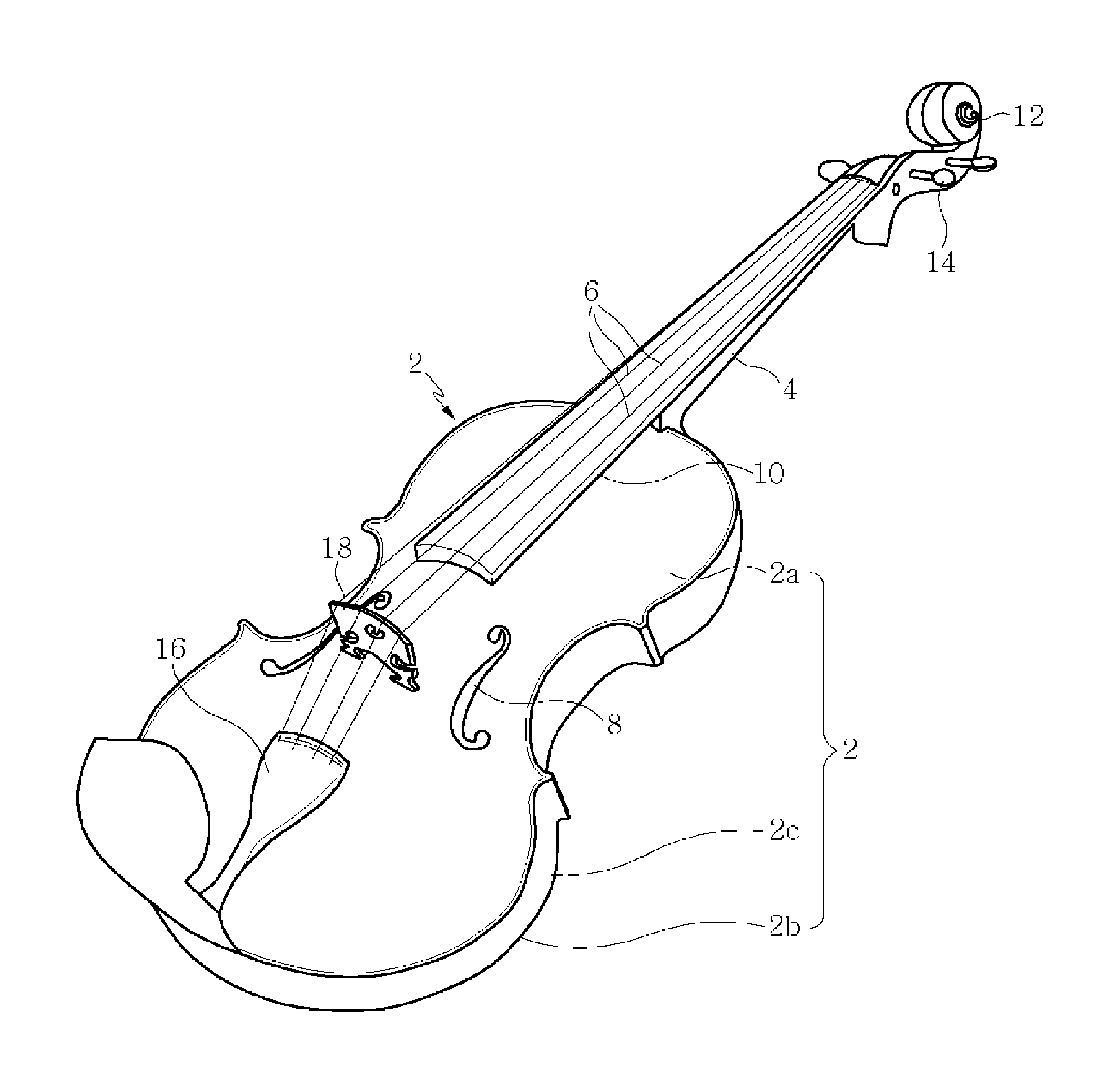
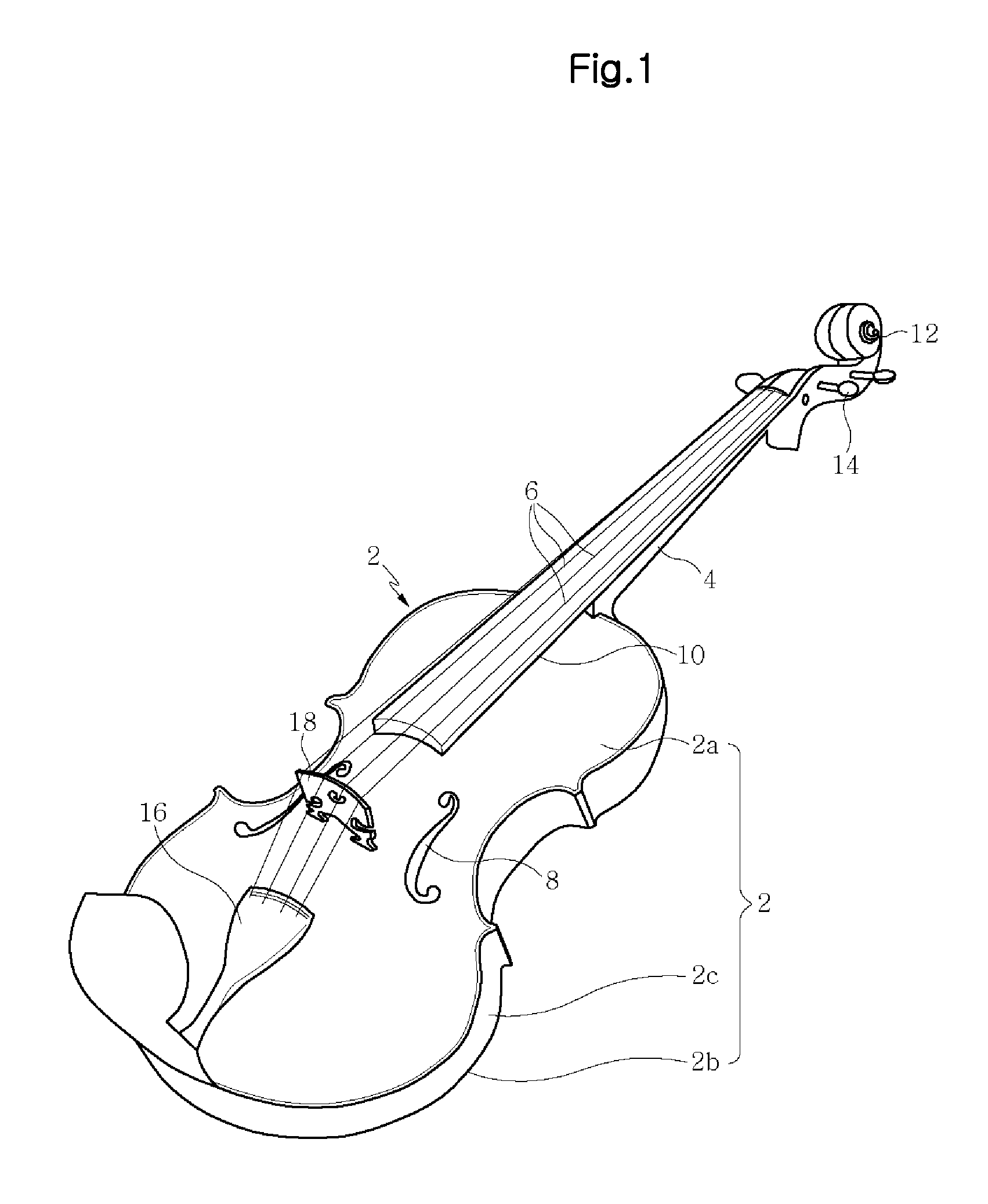
[0027]Hereinafter, an exemplary embodiment of the present invention will be described in more detail with reference to the accompanying drawings. In the following description, it is noted that constituent elements of the present invention respectively corresponding to those of the previously described related art are designated by the same reference numerals. Also, in the following description, a stringed instrument of a violin group according to the present invention may simply be referred to as a violin.

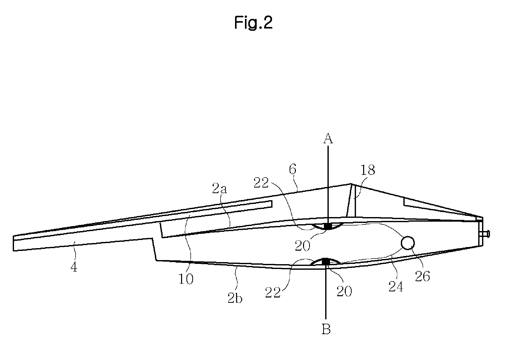
[0028]FIG. 4 is a perspective view of a violin according to the present invention, FIG. 5 is a cross sectional view of FIG. 4, FIG. 6 is an enlarged cross sectional view of a sound post illustrated in FIG. 5, and FIG. 7 is a view illustrating the configuration of a piezoelectric element used in the present invention.

[0029]As illustrated in FIGS. 4 to 6, the acoustic and electric combined stringed instrument of the violin group according to the present invention includes a soundboar...


PUM


Abstract

Disclosed is an acoustic and electric combined stringed instrument of a violin group. The stringed instrument includes a soundboard including upper and lower panels arranged with an interval therebetween and a side panel surrounding the rims of the upper and lower panels, a neck part extending from the soundboard and provided at a distal end thereof with a head, one or more strings secured between the head and the soundboard, and a piezoelectric element to convert vibration and pressure of the strings into electric signals. The piezoelectric element is embedded in the lower panel and secured by a pressure plate, and a sound post is erected on the pressure plate above the piezoelectric element to transmit pressure and vibration from the strings to the pressure plate through a bridge and the upper panel, which enables generation of acoustic sound from the lower panel and amplified sound from the piezoelectric element.

Description

BACKGROUND OF THE INVENTION[0001]1. Field of the Invention[0002]The present invention relates to stringed instruments of a violin group, and more particularly, to acoustic and electric combined stringed instruments of a violin group in which acoustic sound and electric sound can be realized using a single musical instrument.[0003]2. Description of the Related Art[0004]In general, stringed instruments of a violin group are musical instruments configured to produce sound using strings. The stringed instruments may produce sound by friction between strings and hairs of a bow or by thrumming strings using fingers, etc. As illustrated in FIG. 1, a conventional stringed instrument, which is of a type producing sound by friction between strings and hairs of a bow, includes a soundboard 2 defining a cavity for air resonance, a neck part 4 extending from the soundboard 2, and a head part 12 provided at a distal end of the neck part 4. Strings 6 used to produce sound are secured between the s...

Claims


Application Information

Patent Timeline
Patent Type & Authority Applications(United States)
IPC IPC(8): G10H3/18
CPCG10H3/143G10H2220/541G10H3/181
Inventor LEE, JAE-WON
Owner J WONMUSIC
Why Eureka
Try Eureka