Apparatus and method for charging and discharging a dual battery system

a dual-batteries and battery technology, applied in the direction of electric generator control, dynamo-electric converter control, safety/protection circuit, etc., can solve the problems of limiting the range of vehicles, requiring frequent stops for recharging, and limiting the success of such vehicles in everyday us

Pending Publication Date: 2012-04-19
NELSON LARRY
View PDF11 Cites 54 Cited by
  • Summary
  • Abstract
  • Description
  • Claims
  • Application Information

AI Technical Summary

Benefits of technology

[0010]Some embodiments include a drive train that is mechanically coupled between the drive motor and the voltage source. The drive train increases the turning speed of the voltage source relative to the turning speed of the drive motor, preferably by at least a factor of six.

Problems solved by technology

Although momentum is growing in the development and manufacture of electric vehicles, the success of such vehicles in everyday use will continue to be limited if there is no substantial improvement in their range of travel.
Current battery technology used in electric vehicles limits the range of the vehicles, thus requiring frequent stops for recharging.
Some solutions have been proposed in recent years, but they are lacking for various reasons.
This requirement is a significant disadvantage as it adds more weight to the vehicle, and therefore decreases overall efficiency.
Driving a generator through a gearbox attached to a vehicle's wheel as described in this patent is an inefficient way to generate electrical power to recharge vehicle batteries.

Method used


Image

  • Apparatus and method for charging and discharging a dual battery system
  • Apparatus and method for charging and discharging a dual battery system
  • Apparatus and method for charging and discharging a dual battery system

Examples


Embodiment Construction

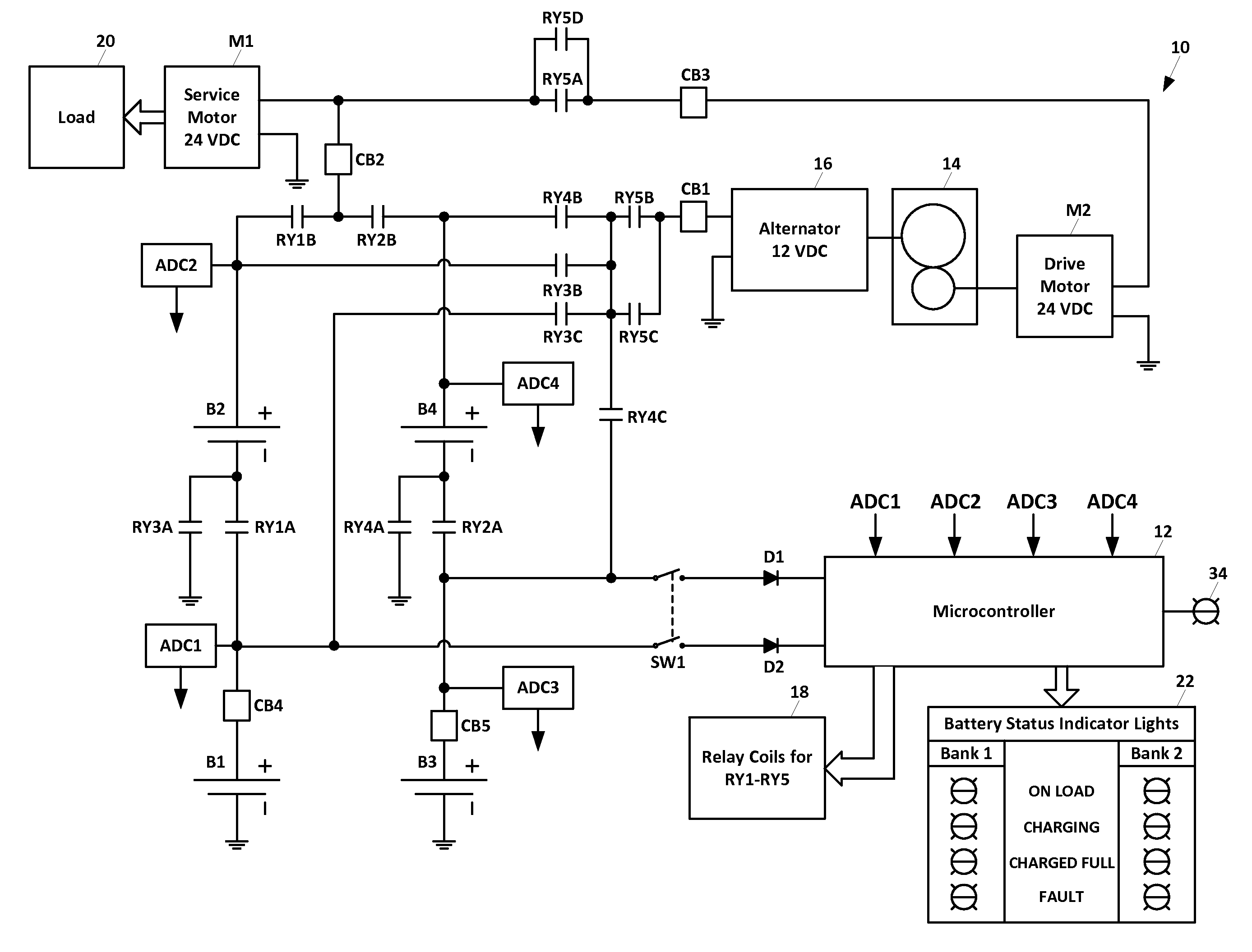
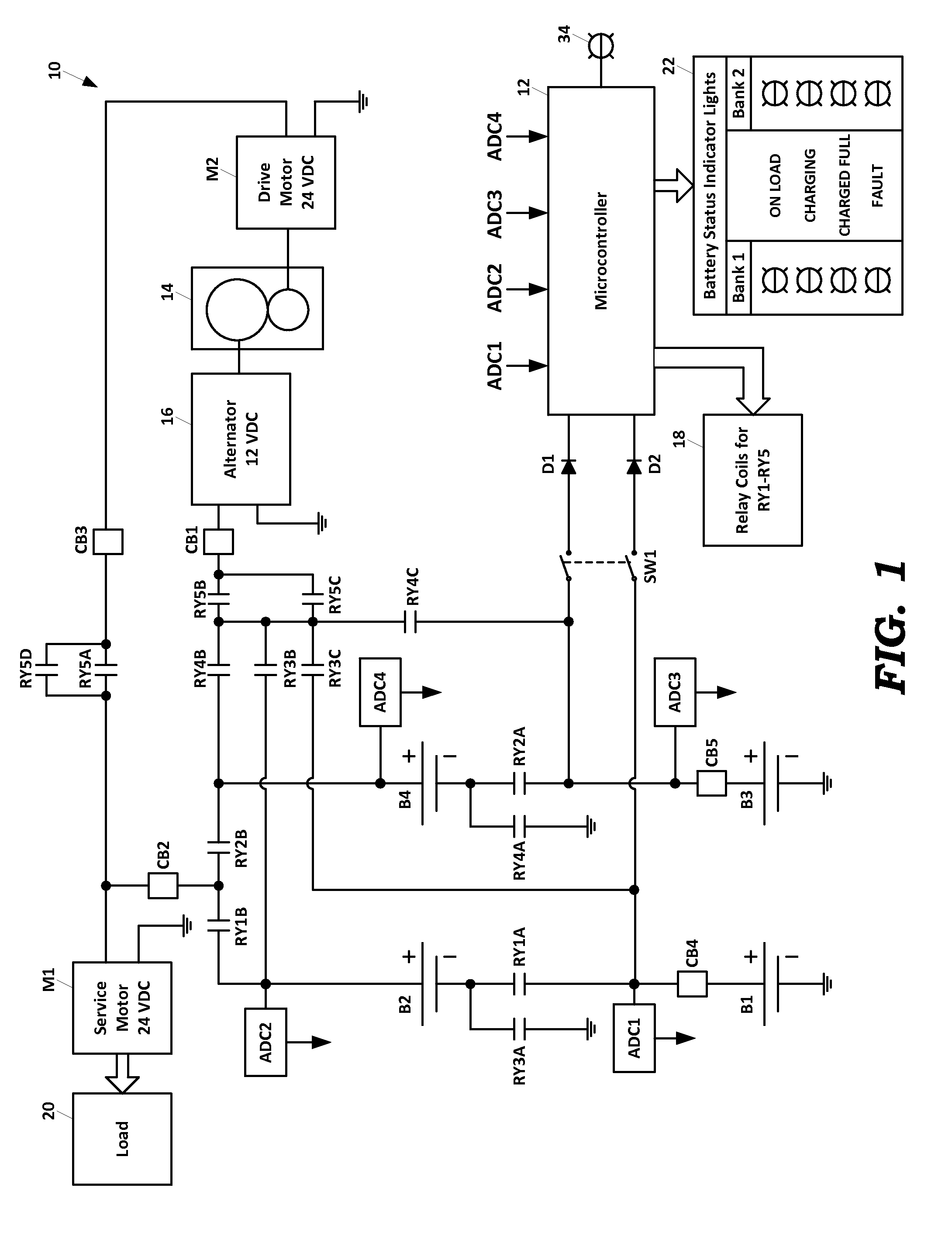
[0024]As the term is used herein, “dual battery” refers to two banks of batteries that are alternately charged and discharged while providing power to an electrical load. Generally, one bank of batteries is used to power the load while the other bank of batteries is being charged or is on standby after charging. Although a preferred embodiment uses two banks of batteries in a charge-discharge rotation, other numbers of battery banks could be used in such a rotation. Thus, it will be appreciated that the invention is not limited to any particular number of battery banks in the charge-discharge rotation.

[0025]As shown in FIG. 1, a preferred embodiment of a dual battery charging-discharging circuit 10 includes four 12 VDC batteries, B1, B2, B3, and B4. The batteries B1 and B2 comprise a first bank of batteries, and batteries B3 and B4 comprise a second bank of batteries. When batteries B1 and B2 are discharging to power the load, they are connected in series to provide 24 VDC. When bat...


PUM


Abstract

A dual battery charging and discharging system controls the configuration of multiple batteries arranged in multiple battery banks. The batteries within each bank are connected in series when powering an electrical load, such as a service motor, and are connected in parallel when charging. A microprocessor monitors the voltage levels of the batteries in each bank and controls relays to switch the electrical load over to a charged battery bank when the voltage level of the discharging battery bank drops below a minimum run threshold. The microprocessor also monitors the voltage levels of the charging battery bank and controls relays to cease charging when the voltage level rises above a minimum charge threshold. The batteries are charged by an alternator driven by a drive motor through a gear reduction system.

Description

RELATED APPLICATIONS[0001]This nonprovisional patent application claims priority to provisional patent application Ser. No. 61 / 394,439 titled APPARATUS AND METHOD FOR CHARGING AND DISCHARGING A DUAL BATTERY SYSTEM filed Oct. 19, 2010, and provisional patent application Ser. No. 61 / 482,881 titled APPARATUS AND METHOD FOR CHARGING AND DISCHARGING A DUAL BATTERY SYSTEM filed May 5, 2011, the entire contents of which are incorporated herein by reference.BACKGROUND[0002]Although momentum is growing in the development and manufacture of electric vehicles, the success of such vehicles in everyday use will continue to be limited if there is no substantial improvement in their range of travel. Current battery technology used in electric vehicles limits the range of the vehicles, thus requiring frequent stops for recharging. Due to the time and effort required to recharge the batteries of an electric vehicle and the limited driving distance of such vehicles on a single charge, there is a need...

Claims


Application Information

Patent Timeline
Patent Type & Authority Applications(United States)
IPC IPC(8): H02K7/18H02P9/00H02J7/14H02K53/00
CPCH02J7/0024H02J7/1423H02J7/1461H02K53/00Y02T10/7055B60L11/1855B60L11/1868Y02T10/7066Y02T10/641Y02T10/7005B60L15/20B60L2240/421B60L2240/547Y02T10/72B60L58/19B60L58/14B60L58/22B60L58/20Y02T10/64Y02T10/70H02J7/00304H02J7/0049
Inventor NELSON, LARRY
Owner NELSON LARRY
Why Eureka
Try Eureka