Method for operating an energy generator with inverter operation depending on a mains voltage and circuit layout

Active Publication Date: 2012-04-19
BOB HLDG GMBH
View PDF3 Cites 8 Cited by
  • Summary
  • Abstract
  • Description
  • Claims
  • Application Information

AI Technical Summary

Benefits of technology

[0014]It is therefore an object of the present invention to contribute to

Problems solved by technology

Thus untapped possibilities are also to be utilized of using invert

Method used


Image

  • Method for operating an energy generator with inverter operation depending on a mains voltage and circuit layout
  • Method for operating an energy generator with inverter operation depending on a mains voltage and circuit layout
  • Method for operating an energy generator with inverter operation depending on a mains voltage and circuit layout

Examples


Example

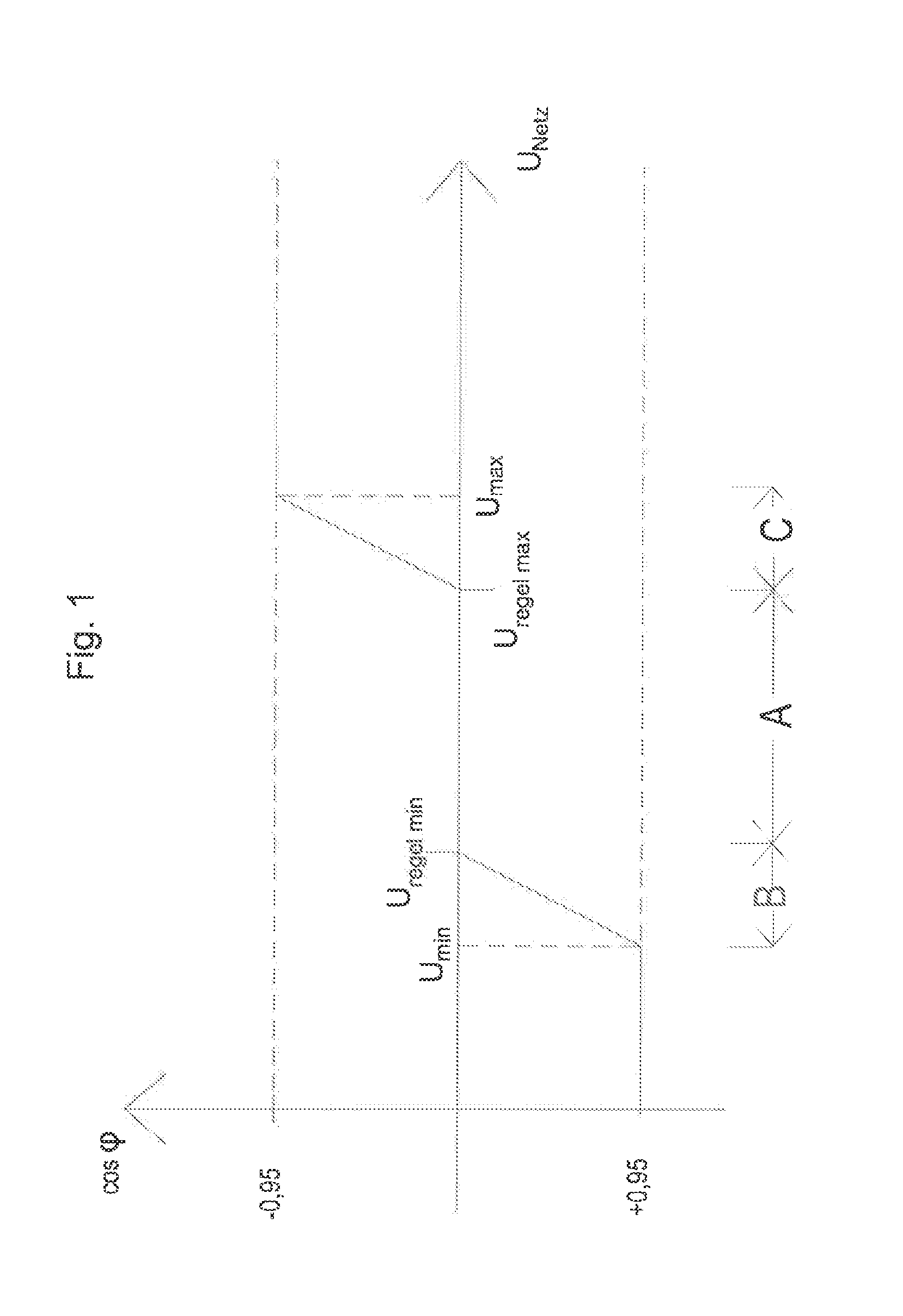
[0052]FIG. 1 shows this type of control diagram of the cos phi (cos φ) over the inverter output voltage U, which in principle is advantageously used with modern PV plants and which is intended to facilitate understanding of the following description.

[0053]Two limit values Umin and Umax are provided, which in general are not to be fallen below or exceeded. Between these boundary limit values Umin and Umax lies a linear control range A, which is delimited by two control limit values Uregel min and Uregel max. In this range A the plant is operated cos phi neutral and pure active power is fed into the electrical grid. If the operating point of the inverter with its output voltage U is in the range B between Umin and Uregel min, in addition reactive power kvar (Kilovolt-amperes reactive) is supplied to the electrical grid.

[0054]Analogously, with an operating point of the inverter with an output voltage U in the range C between Umax and Uregel max in addition to the power feed-in, reactiv...


PUM


Abstract

A method for operating a first energy generator in an electric power supply system to which a plurality of electric consumers and at least the first energy generator, which is embodied as a regenerative energy generator, are connected via respectively one grid connection point each assigned thereto, wherein at least the first energy generator has an inverter of predetermined power rating, the AC voltage output of which is electrically connected to a first grid connection point assigned thereto, and wherein the operating control of the inverter regarding its reactive power feed and/or its reactive power draw into or out of the electric power supply system takes place depending on a continuously measured mains voltage value. The reactive power control in the energy grid is improved in that the mains voltage value is measured at a second grid connection point, which is different from the first grid connection point of the energy generator.

Description

[0001]This nonprovisional application claims priority under 35 U.S.C. §119(a) to German Patent Application No. DE 10 2010 047 652.8, which was filed in Germany on Oct. 6, 2010, and which is herein incorporated by reference.BACKGROUND OF THE INVENTION[0002]1. Field of the Invention[0003]The invention relates to a method for operating a first energy generator in an electric power supply system to which a plurality of electric consumers and at least the first energy generator, which in particular is embodied as a regenerative energy generator, are connected via respectively one grid connection point each assigned thereto, wherein at least the first energy generator has an inverter of predetermined power rating, the AC voltage output of which is electrically connected to a first grid connection point assigned thereto, and wherein the operating control of the inverter regarding its reactive power feed and / or its reactive power draw into or out of the electric power supply system takes pl...

Claims


Application Information

Patent Timeline
IPC IPC(8): H02J3/14
CPCH02J3/18Y02E40/30Y02E10/563H02J3/50H02J3/46Y02E10/56
Inventor BECK, BERNHARD
Owner BOB HLDG GMBH
Why Eureka
Try Eureka