Electrical machine

a technology of electric machines and parts, applied in the field of electric machines, can solve the problems of waste of sheet metal parts, inability to use, and inability to heat the electrical machine, and achieve the effect of minimizing was

Active Publication Date: 2012-04-19
ROBERT BOSCH GMBH
View PDF10 Cites 3 Cited by
  • Summary
  • Abstract
  • Description
  • Claims
  • Application Information

AI Technical Summary

Benefits of technology

[0006]The object of the invention is therefore to provide a laminated core for an electrical machine, in which waste is minimized during production of the laminated core, it being possible to produce said laminated core in a simple manner, to mount said laminated core in the electrical machine and to use said laminated core both on the stator and on the rotor of an electrical machine.
[0007]According to the invention, it has been identified that a high proportion of material being wasted can be avoided during production of a laminated core with a rectangular cross section of a rotor and / or a stator of an electrical machine by the laminated core having a continuous sheet metal strip which forms a hollow-cylindrical body when wound in the form of a coil. In this way, the material weight used can be reduced by approximately one order of magnitude compared to the punching method used. Furthermore, the sheet metal strip which is wound in the form of a coil facilitates mounting in the rotor or stator.
[0008]In a further embodiment of the invention, the electrical machine has a support on the stator and / or on the rotor, said support having at least one receptacle, and with the prestress of the wound sheet metal strip of the laminated core being set such that the laminated core is arranged in the receptacle of the support of the stator and / or of the rotor without play. This has the advantage that the laminated core is automatically matched to the manufacturing dimensions of the support.
[0009]In a further embodiment of the invention, the sheet metal strip of the laminated core is connected in the axial direction at least partially by means of baked enamel or by means of a weld connection. In this way, the moving and flexible laminated core can be fused and / or welded to form a strong structure.

Problems solved by technology

In this case, inductively generated eddy currents, which lead to heating of the electrical machine and furthermore cannot be used, are produced under the influence of an alternating electrical field in iron cores comprising solid material.
When the sheet metal part is punched out, both the inner part of the sheet metal part and the outer part of the sheet metal part, that is the remains of the sheet metal strip, are wasted.
On account of the two-part design of the cut strip-wound core, said cut strip-wound core is particularly unsuitable for use in rotating electrical machines.
The cut strip-wound core is primarily unsuitable for use on the rotor since the metal sheets are exposed to high centrifugal forces here.

Method used


Image

  • Electrical machine
  • Electrical machine
  • Electrical machine

Examples


first embodiment

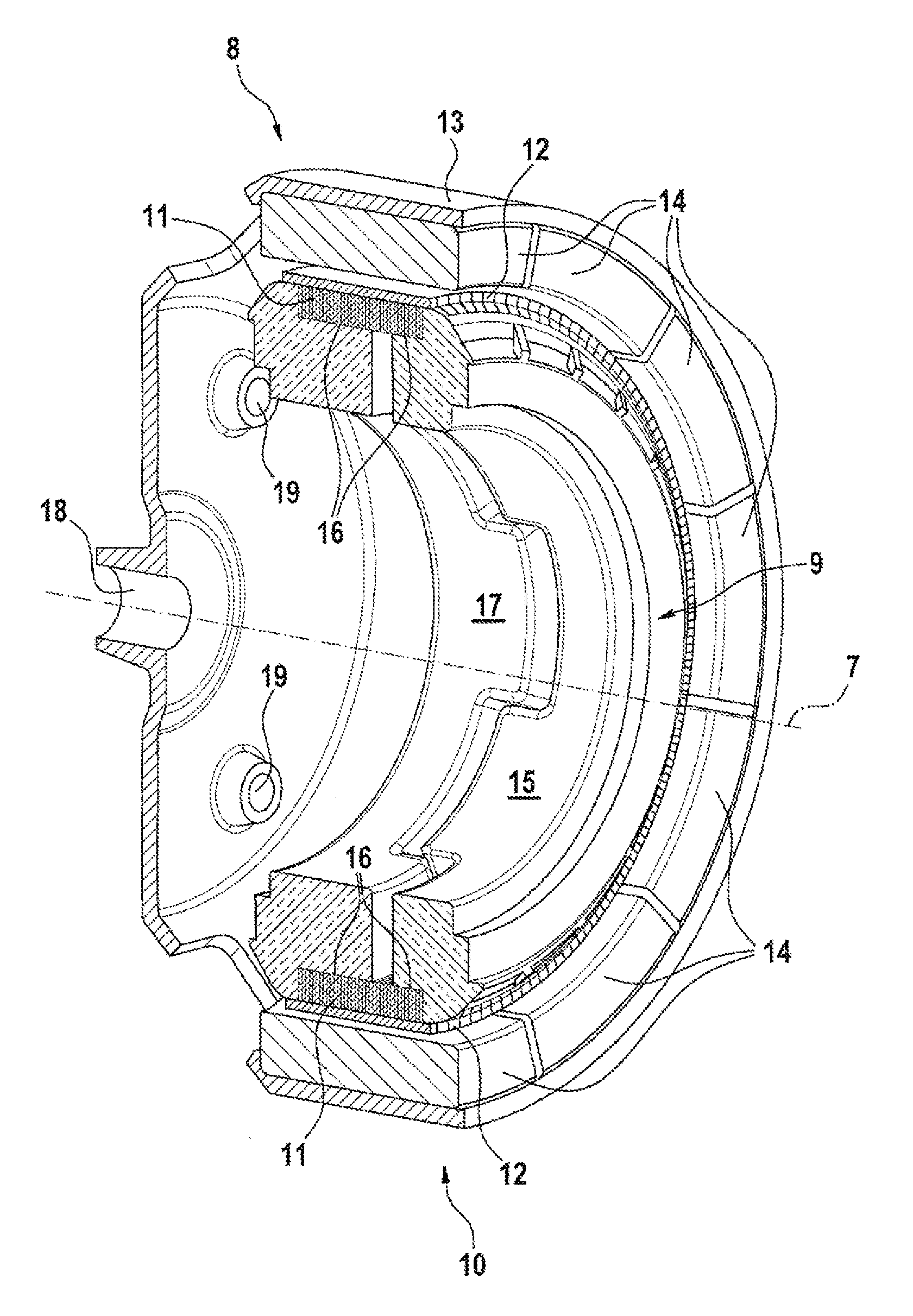
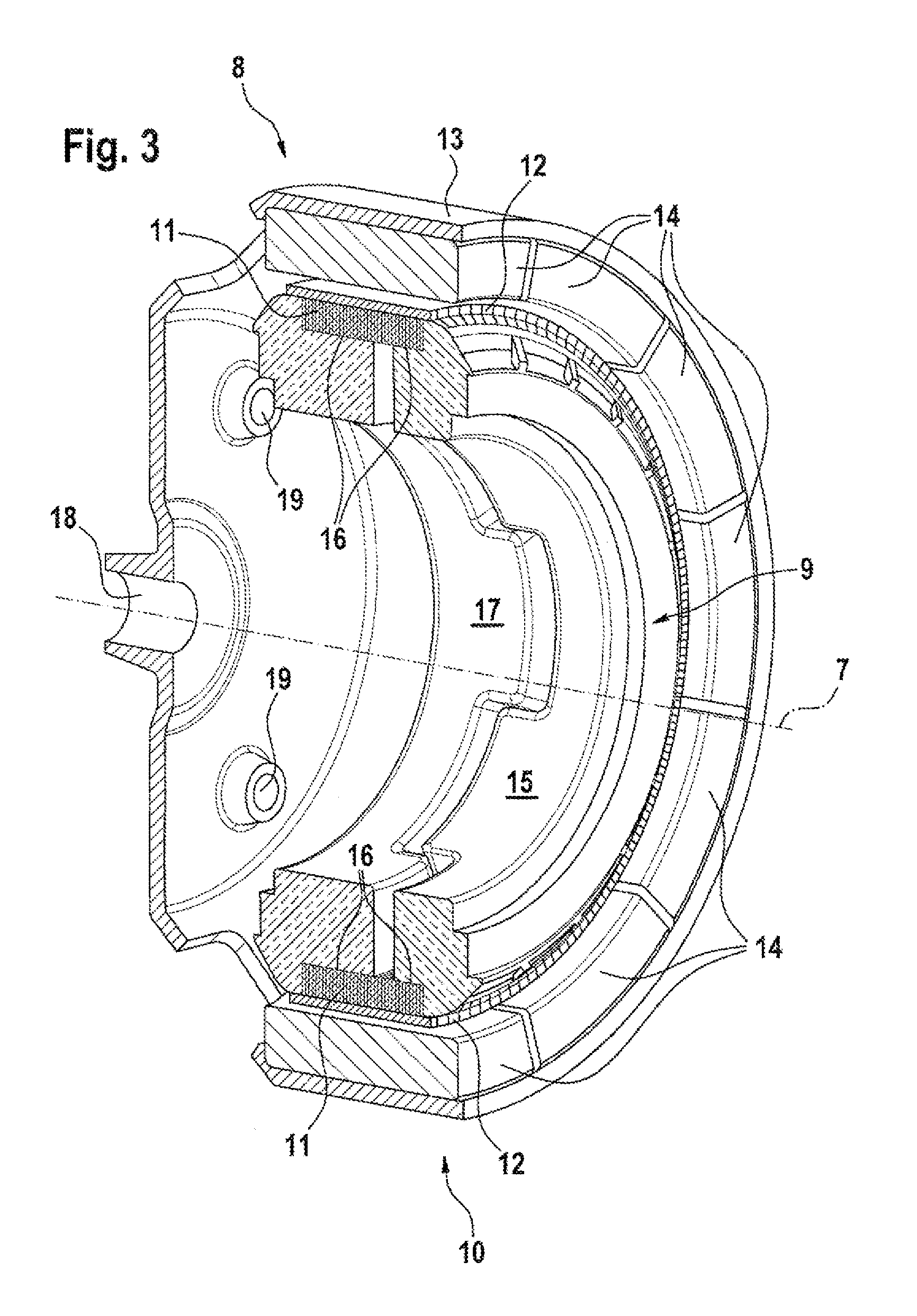
[0022]FIG. 3 is a schematic 3D illustration of an electrical machine according to a The electrical machine, which is illustrated in a three-dimensional half-section, is designed as a brushless DC machine which has a rotor 8 which, as an external rotor 10, at least partially surrounds a stator 9. The rotor 8 has a bell 13 with a central opening 18 for receiving a shaft (not illustrated) which lies on the rotation axis 7. Fastening openings 19 are provided in the bell for the purpose of transmitting the generated torque of the external rotor 10, said fastening openings ideally being arranged concentrically about the rotor axis 7. Three fastening openings 19 with an angular offset of 120° are provided around the rotation axis 7 in the illustrated exemplary embodiment, said fastening openings having conical reinforcements at their side faces, said reinforcements projecting into the space in the bell 13 of the rotor 8.

[0023]The magnets 14 are arranged on the inside over the circumferent...

third embodiment

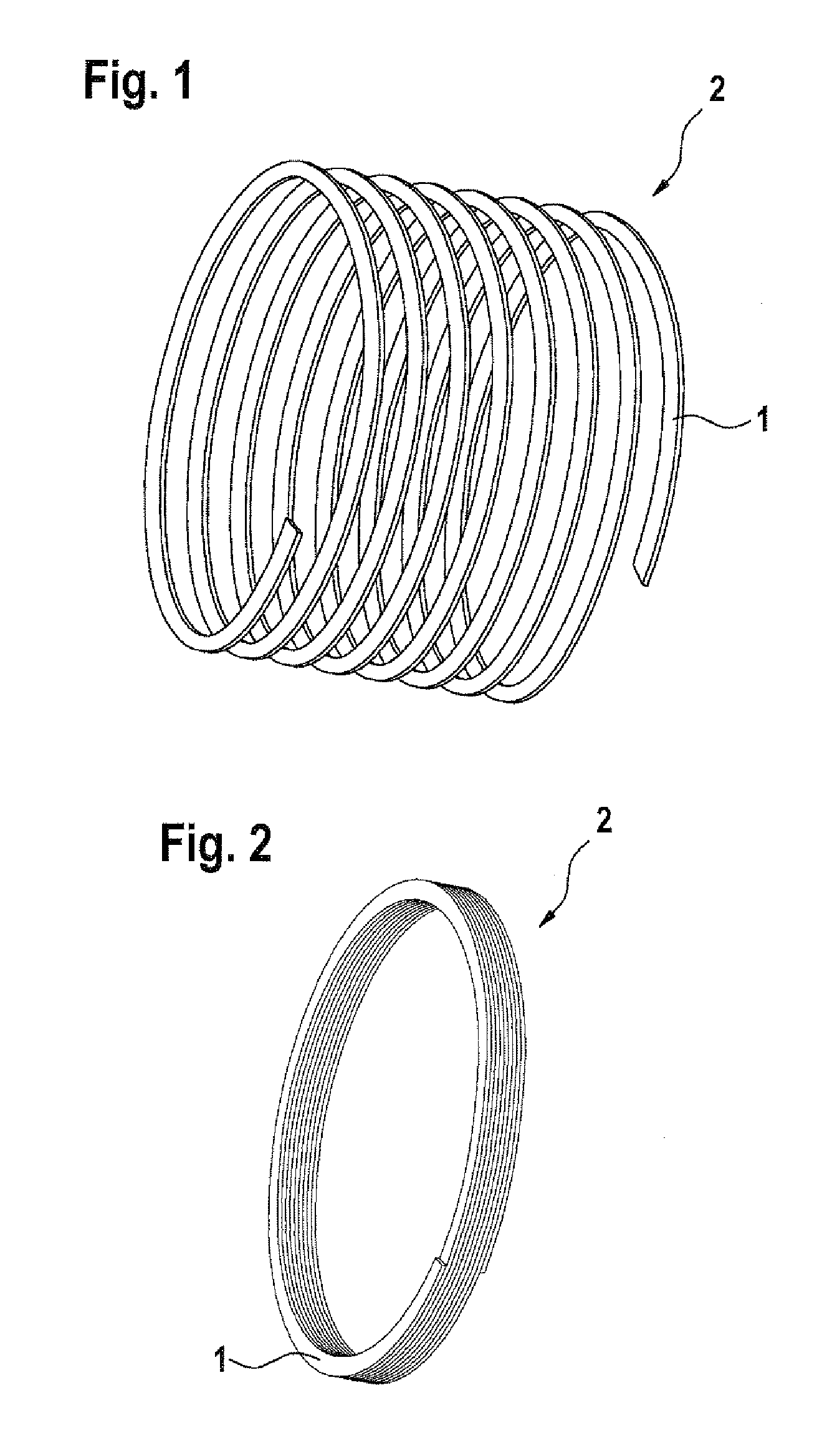
[0033]FIG. 5 shows a cross section through an electrical machine according to the invention. In this case, the electrical machine comprises a rotor 76 and a stator 77. In the embodiment, the rotor 76 is designed as an internal rotor and the stator 77 has a typical pole shoe construction. The rotor 76 has a support 70 which is arranged on a rotor shaft (not illustrated). The support 70 is radially surrounded by a laminated core 72. The laminated core 72 is produced from a sheet metal strip 72 which is wound around a mandrel in a similar way to the laminated core 2 from FIGS. 1 and 2. The sheet metal strip can also comprise flat wire. The laminated core 72 can be stressed by twisting one end of the laminated core 72 about the longitudinal axis of the laminated core 72 in relation to the other end of the laminated core 72, with the inside diameter of the laminated core 72 increasing in size in the process. In the prestressed state, the laminated core 72 can be mounted on the support 70...


PUM

PropertyMeasurementUnit
weightaaaaaaaaaa
thicknessaaaaaaaaaa
diameteraaaaaaaaaa

Abstract

The invention relates to an electric machine, comprising a rotor (8; 50; 76) and a stator (9; 29; 77), wherein the rotor (8; 50; 76) and / or the stator (9; 29; 77) comprise at least one laminated core (2; 11; 32; 72) having a substantially rectangular cross-section, wherein the laminated core (2; 11; 32; 72) comprises a sheet metal strip (1), wherein the sheet metal strip (1) is wound in a coil shape.

Description

BACKGROUND OF THE INVENTION[0001]The invention relates to an electrical machine having a housing containing a rotor and a stator, with the rotor and / or the stator having at least one laminated core with a substantially rectangular cross section.[0002]Iron cores are used in a very wide variety of types of electrical machines for conducting the magnetic flux with a low level of loss. In this case, inductively generated eddy currents, which lead to heating of the electrical machine and furthermore cannot be used, are produced under the influence of an alternating electrical field in iron cores comprising solid material. In order to minimize this, iron cores for electrical machines are preferably formed from metal sheets which are electrically insulated from one another or as cut strip-wound cores. In this case, the insulated metal sheets are either constructed as individual, loose metal sheets, also called laminations, or as an interconnected laminated core, also called stack of lamina...

Claims


Application Information

Patent Timeline
Patent Type & Authority Applications(United States)
IPC IPC(8): H02K1/30H02K15/02
CPCH02K1/12H02K1/22Y10T29/49012Y10T29/49009H02K15/026
Inventor KRAUTH, WOLFGANGKOENIG, TILO
Owner ROBERT BOSCH GMBH
Why Eureka
Try Eureka