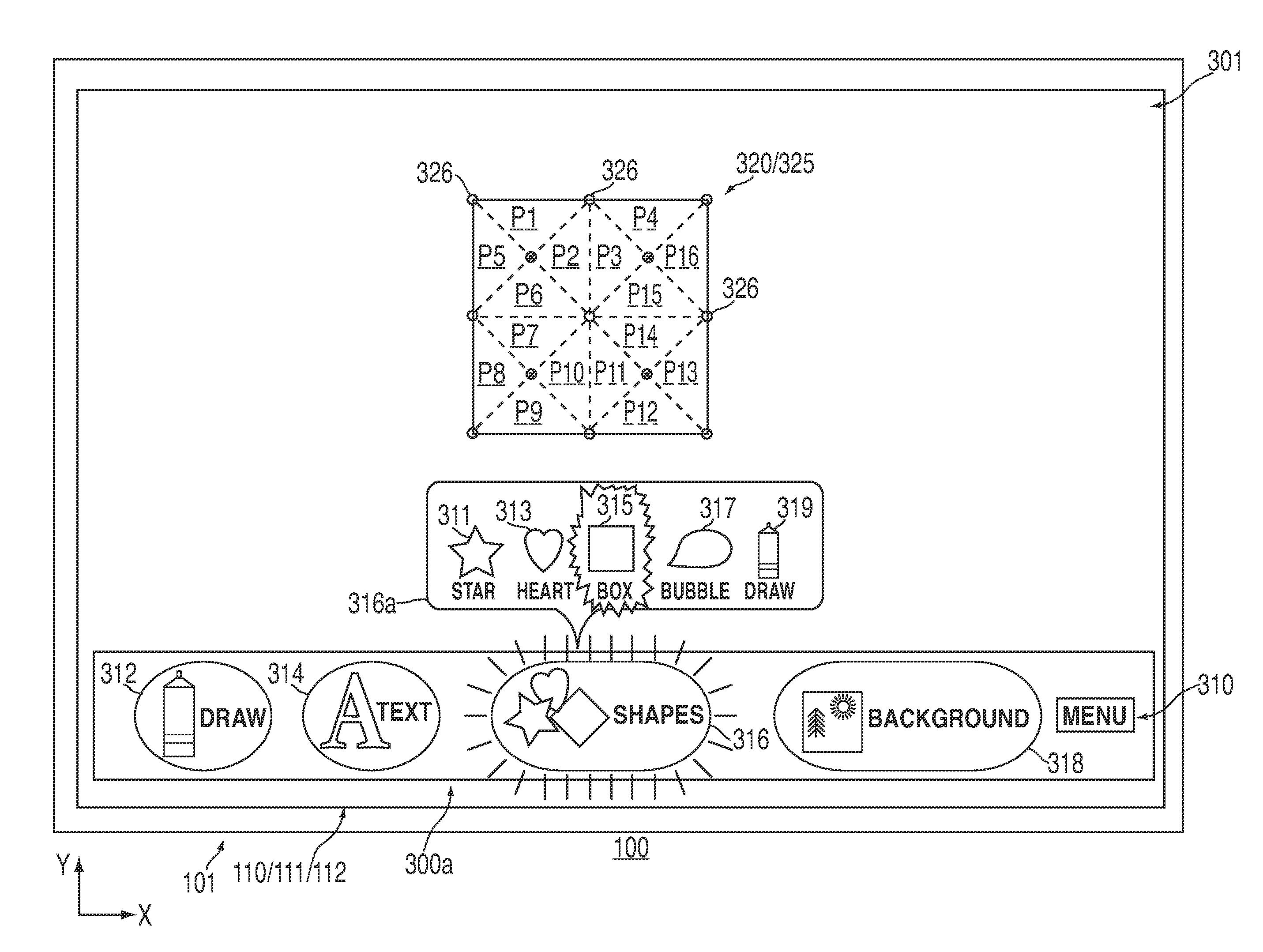
[0006]In other embodiments, there is provided a method for manipulating graphical data that may include generating graphical object content. The graphical object content may include a first character glyph and a second character glyph of a text string. The method may also include modeling a polygonal mesh based on the graphical object content, and then rendering on a display both a graphical object based on the graphical object content and a map of control points based on the polygonal mesh.
[0007]For example, in some embodiments, the polygonal mesh may be modeled by generating a first intra-character polygon for the first character glyph, generating a second intra-character polygon for the second character glyph, and generating a first inter-character polygon between the first intra-character polygon and the second intra-character polygon. For example, the first intra-character polygon and the second intra-character polygon may share a common vertex, the first inner-character polygon and the first intra-character polygon may share two common vertices, while the first inner-character polygon and the second intra-character polygon may share two common vertices. In other embodiments, the polygonal mesh may be modeled with respect to a baseline typographical bound and an ascent typographical bound. For example, each intra-character polygon may include two baseline vertices and an ascent vertex, and one of the two baseline vertices of each of intra-character polygon may be a common baseline vertex to both intra-character polygons. Moreover, the first inner-character polygon may include the common baseline vertex of both intra-character polygons as well as the ascent vertex of each intra-character polygon. Each polygon may include a set of constraints, and each constraint of each intra-character polygon may be rigid, while a constraint of the first inner-character polygon may be non-rigid. In such embodiments, each polygon may include a set of vertices, while a common vertex may be shared by the first intra-character polygon, the second intra-character polygon, and the first inner-character polygon. The non-rigid constraint of the first inner-character polygon may prevent a constraint of the first intra-character polygon from overlapping with a constraint of the second intra-character polygon when the graphical object is manipulated. The polygonal mesh may include multiple vertices and each vertex may be associated with a respective one of the control points.
[0008]In other embodiments, there is provided a method that may include presenting for display on a virtual drawing space a graphical object that may include multiple control points, each of which may be moveable between and anchorable to coordinates on the virtual drawing space. The method may also include simultaneously accepting a first user input for moving a first control point to a first user-designated coordinate and a second user input for moving a second control point to a second user-designated coordinate. Then, in response to the user inputs, the method may also include simultaneously moving the first control point along the virtual drawing space to the first user-designated coordinate, the second control point along the virtual drawing space to the second user-designated coordinate, and at least some of the other control points along the virtual drawing space in an inertial manner. For example, the first user input and the second user input may be simultaneously received from a multi-touch input component. In some embodiments, the first user input and the second user input may be simultaneously received by moving a virtual user input tool along the virtual drawing space in a single direction. In some embodiments, the method may also include anchoring the first control point at the first user-designated coordinate.
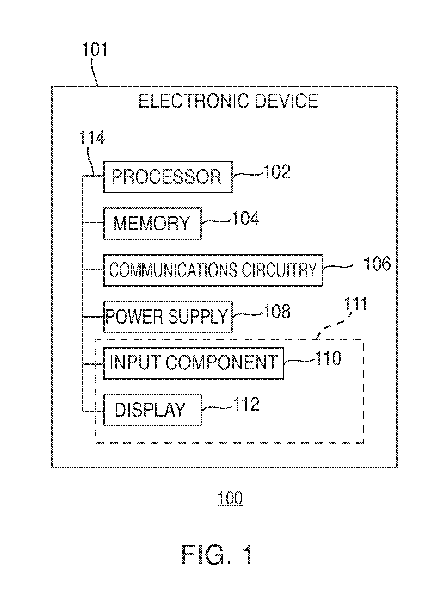
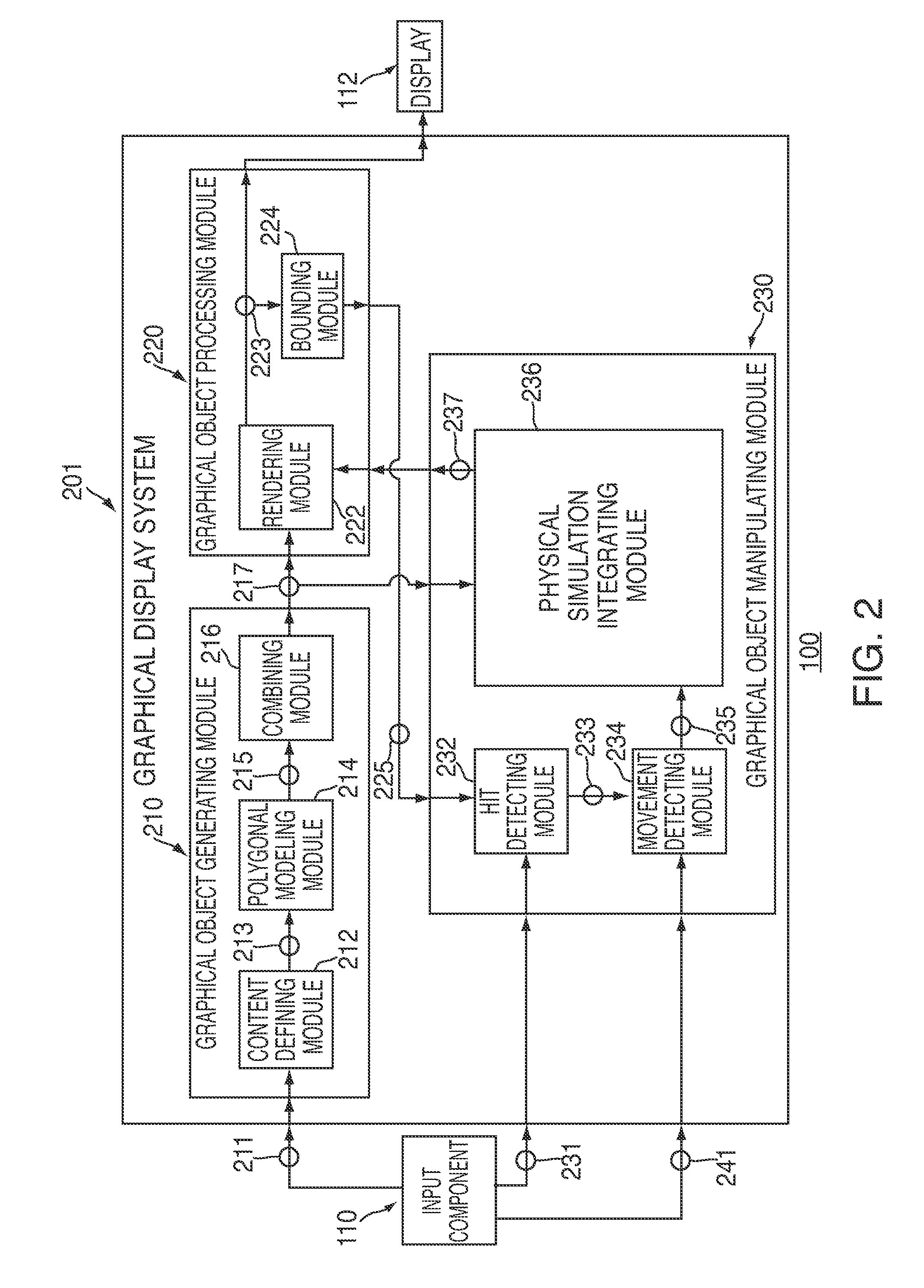
[0009]In still yet other embodiments, there is provided a graphical display system. The system may include a polygonal modeling module that may generate a collection of polygons based on graphical object content, and a rendering module that may render a graphical object on a display based on the graphical object content and that may render at least two control points on the display based on the collection of polygons. The system may also include a hit detecting module that may receive activation information for each of the at least two control points, and a movement detecting module that may receive movement information. The system may also include a physical simulation integrating module that may physically simulate the collection of polygons based on the activation information and the movement information.
[0010]For example, in some embodiments, the system may also include a re-rendering module that may re-render the graphical object and the at least two control points based on the physically simulated collection of polygons. A multi-touch input component may also be included, such that the hit detecting module may simultaneously receive the activation information for each of the at least two control points from the multi-touch input component. Similarly, the movement detecting module may receive the movement information from the multi-touch input component. The graphical object content may include a first character glyph and a second character glyph of a text string. In other embodiments, the graphical object content may include a boundary of a drawing shape.
[0011]In still yet other embodiments, there is provided computer-readable media for controlling an electronic device. The media may include computer-readable code recorded thereon for generating graphical object content that may include a first character glyph and a second character glyph of a text string. The media may also include computer-readable code recorded thereon for modeling a polygonal mesh based on the graphical object content by generating a first intra-character polygon for the first character glyph, generating a second intra-character polygon for the second character glyph, and generating a first inter-character polygon between the first intra-character polygon and the second intra-character polygon. The media may also include computer-readable code recorded thereon for rendering on a display both a graphical object based on the graphical object content and a map of control points based on the polygonal mesh. In some embodiments, each polygon may include at least three vertices, and each control point may be associated with a respective vertex.


