Extruded wide angle lens for use with a LED light source

a wide angle lens and led light source technology, applied in applications, lighting and heating apparatus, instruments, etc., can solve the problems of not being able to provide led modules, not being able to achieve light patterns, and not being able to achieve the effect of maximizing the total efficiency of the lens

Active Publication Date: 2012-04-19
SIGNIFY HLDG BV
View PDF2 Cites 31 Cited by
  • Summary
  • Abstract
  • Description
  • Claims
  • Application Information

AI Technical Summary

Benefits of technology

[0003]A light fixture can include a LED light source. Because light provided by a LED light source may typically have a limited distribution, the light fixture can include a lens for re-distributing emitted light to a wide angle. The lens can include an elongated structure having a primary lens surface opposite a secondary lens surface, where the LED light source is placed adjacent to the primary light source. The elongated structure can include at least two distinct protrusions extending from a planar section, where the protrusions re-direct light emitted from the LED light source to a wide angle. The two distinct protrusions can form part of a twin lens. In particular, the lens can be constructed to use the total internal reflection (TIR) to maximize the total efficiency of the lens. The elongated structure can include a notch in the outer surface of the lens (e.g., in the secondary lens surface) between the protrusions, such that the notch is opposite the LED light source.

Problems solved by technology

This illumination pattern, however, may not be desirable for ceiling light fixtures, or other fixtures for which it is desirable that light is distributed using a wide angle pattern.
In particular, this light pattern may not be desirable for LED modules provided on a top surface of a hanging fixture, where the LED modules illuminate a ceiling.

Method used


Image

  • Extruded wide angle lens for use with a LED light source
  • Extruded wide angle lens for use with a LED light source
  • Extruded wide angle lens for use with a LED light source

Examples


Embodiment Construction

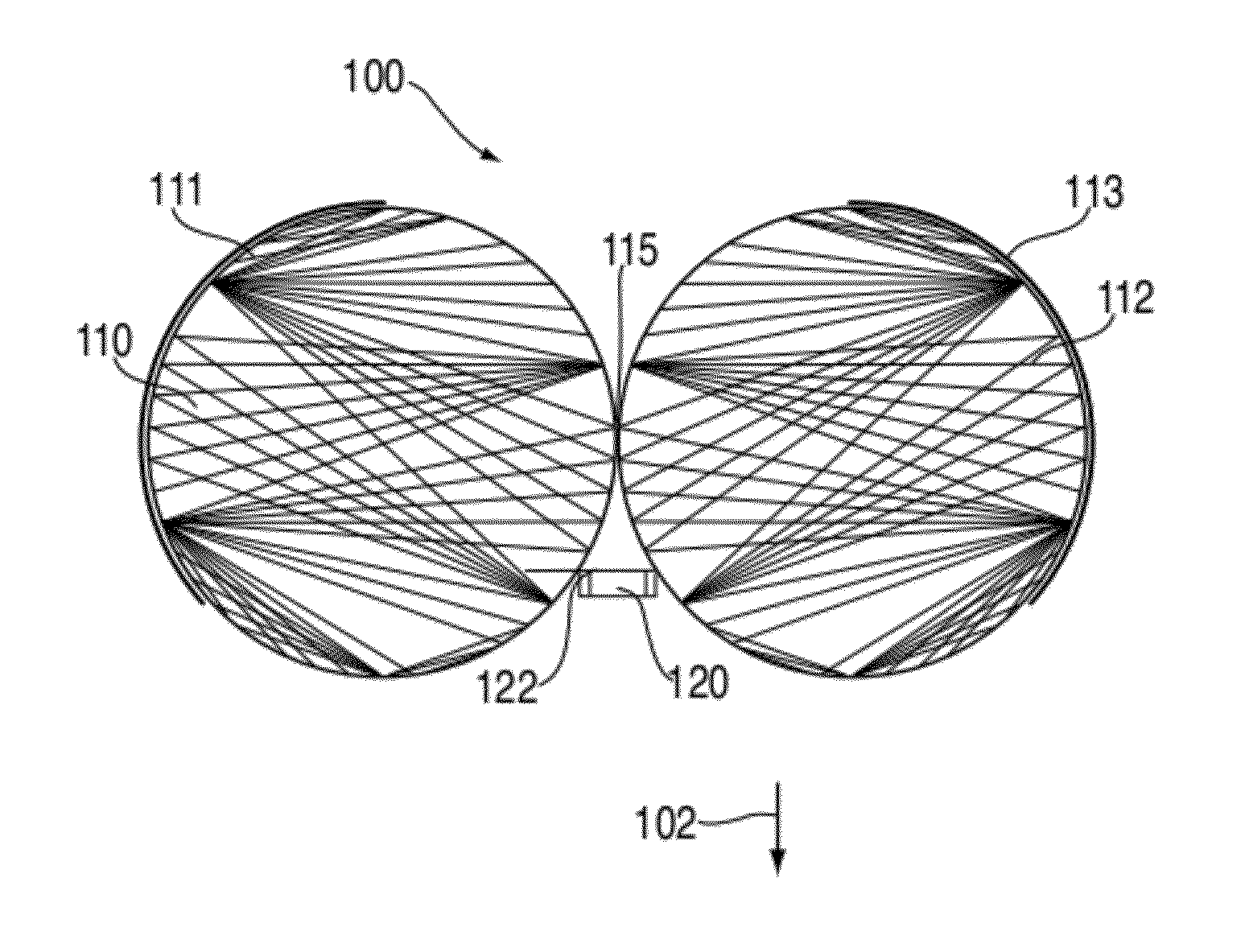
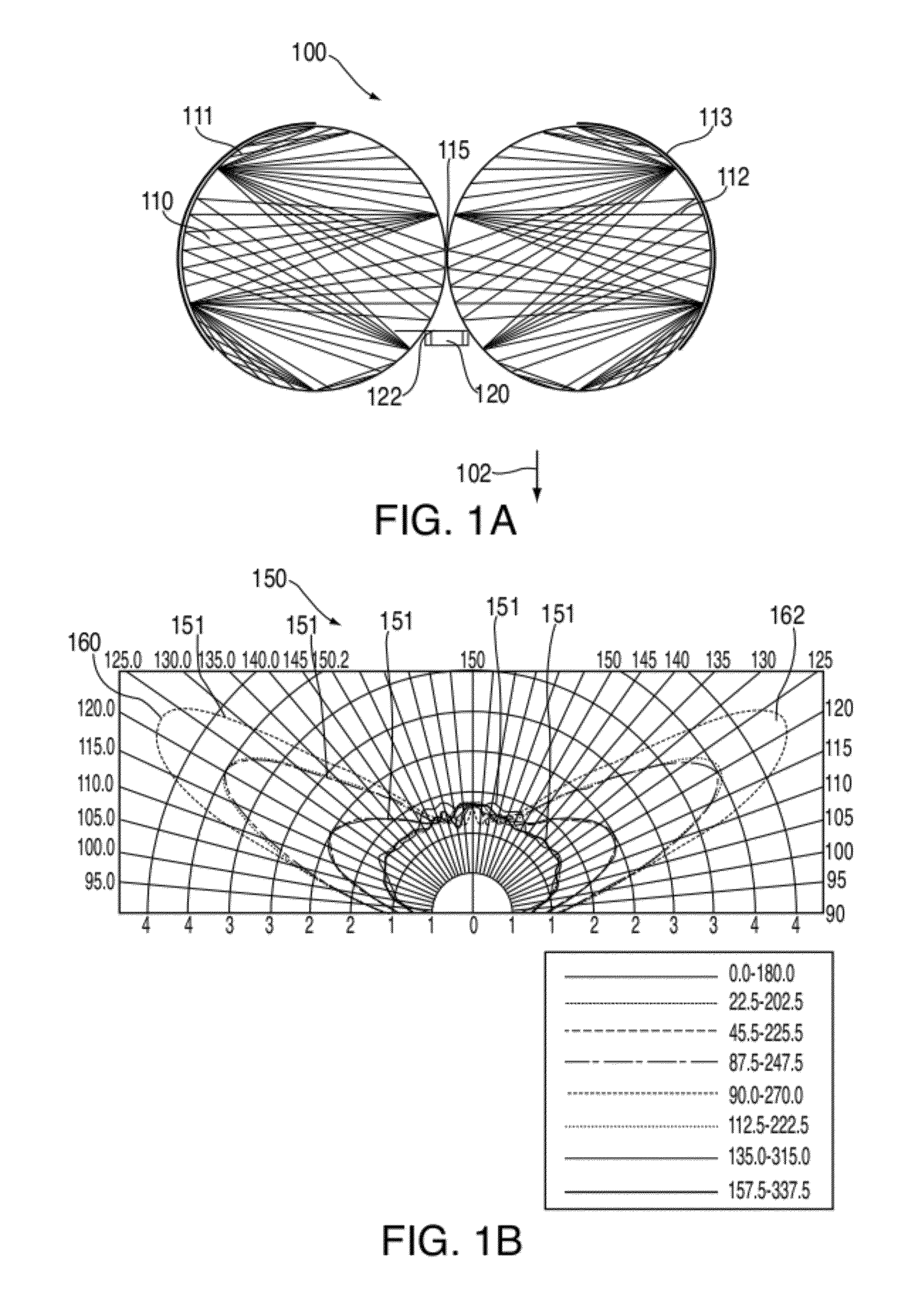
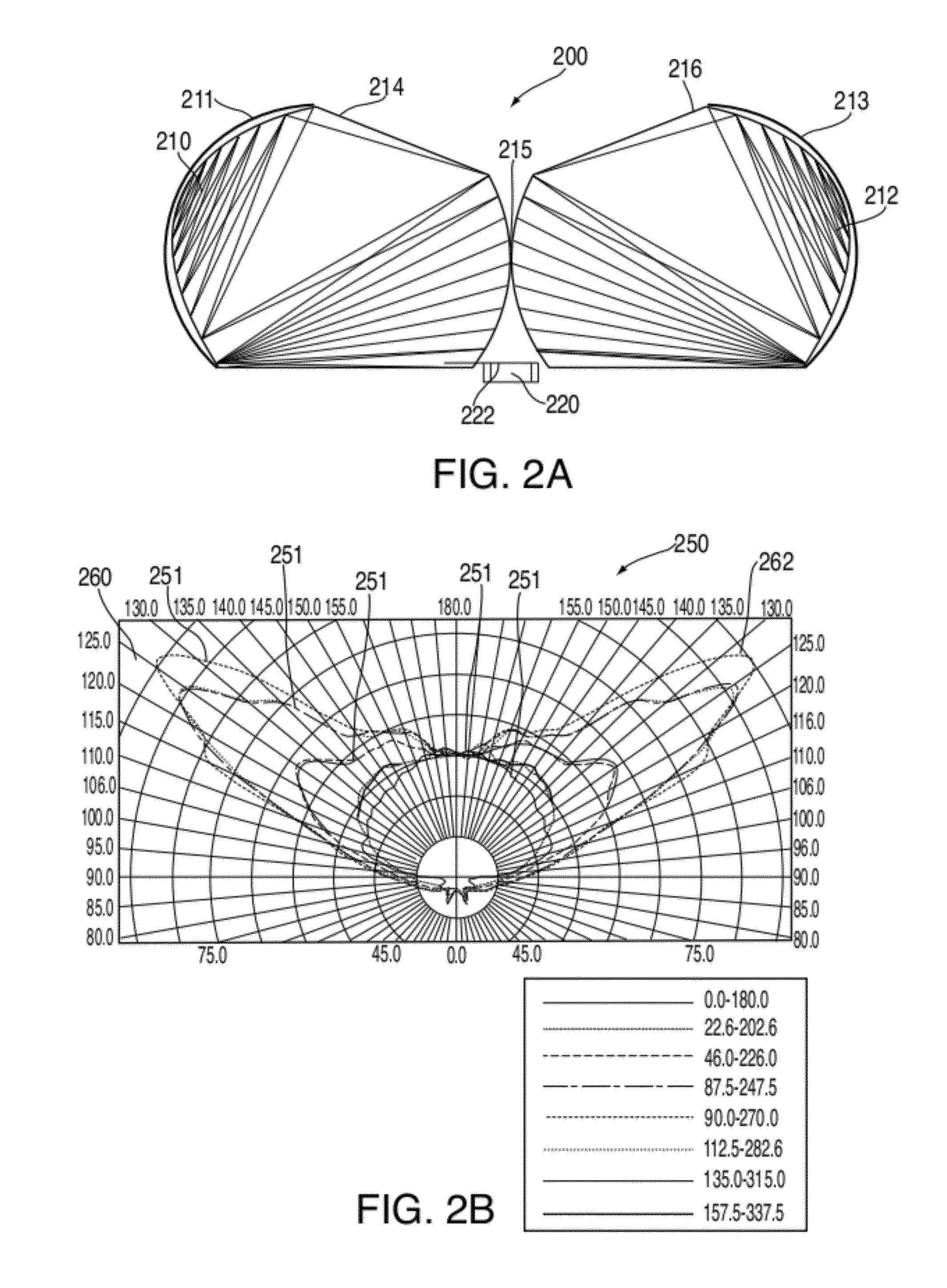
[0030]This is directed to a wide-angle lens for shifting the distribution of light emitted by a LED light source. In particular, this is directed to a lens operative to re-direct light from a tight angle to a wide angle relative to a normal to a light emitting surface of a LED light source.

[0031]A light fixture using a LED module as a light source can be mounted in several different manners. In some cases, a light fixture can be mounted to a ceiling, mounted under a counter, as part of a desk light, a wall scone, a wall wash, as a surface mounted light fixture, or combinations of these. To ensure that light emitted from the fixture is distributed in a manner that effectively illuminates a space and provides an even lighting pattern, the distribution pattern of light emitted by a LED module of the fixture can be tailored for a type of light fixture or for a particular environment.

[0032]Different approaches can be used to change a distribution pattern of light emitted by a LED module....


PUM

PropertyMeasurementUnit
angleaaaaaaaaaa
half angleaaaaaaaaaa
critical angleaaaaaaaaaa

Abstract

This is directed to a lens for use with a LED light source. The lens can be placed on a top surface of a light fixture to direct light emitted by a LED module at a wide angle relative to the top surface of the fixture. The lens can include an elongated trench in which several LED light sources can be placed in a line such that light emitted within the trench is re-directed by the lens. The lens can include one or more knobs extending over the trench to facilitate diverting emitted light in a more lateral direction, as opposed to vertical direction. In some cases, the lens can be constructed using an extrusion process by which a lens having a constant cross-section allowing for a wide angle radiation pattern is provided.

Description

BACKGROUND[0001]A LED light source can be constructed from a LED module placed in a fixture having a lens. The lens can serve to direct light from the LED module to an environment in which the LED light source is placed. A LED module typically distributes light in a Lambertian radiation pattern. In other words, the majority of the light emitted by the LED module is within a half angle of 60 degrees from the vertical axis of an emitting face of the LED module. This illumination pattern, however, may not be desirable for ceiling light fixtures, or other fixtures for which it is desirable that light is distributed using a wide angle pattern. In particular, this light pattern may not be desirable for LED modules provided on a top surface of a hanging fixture, where the LED modules illuminate a ceiling. Instead, it may be desirable for light emitted by the LED modules to be shifted such that the emitted light falls in a region substantially near a plane of the emitting face of the LED mo...

Claims


Application Information

Patent Timeline
Patent Type & Authority Applications(United States)
IPC IPC(8): F21S8/04B29D11/00F21V5/00
CPCB29D11/00009F21S4/008F21S8/04F21S8/06F21V5/04G02B19/0061F21V13/02F21Y2101/02F21Y2103/003G02B19/0071G02B19/0028F21V7/0091F21S4/28F21Y2103/10F21Y2115/10
Inventor ZHANG, JOHN X.LOWERY, CHRISTOPHER H.
Owner SIGNIFY HLDG BV
Why Eureka
Try Eureka