Sheet-discharge apparatus, sheet processing apparatus, and image forming apparatus

a technology of image forming apparatus and discharge apparatus, which is applied in the direction of electrographic process apparatus, thin material handling, instruments, etc., can solve the problems of reducing the alignment properties of the sheet on the stacking tray, and reducing so as to prevent the reduction of the alignment properties of the sheet without reducing productivity

Active Publication Date: 2012-04-19
CANON KK
View PDF11 Cites 24 Cited by
  • Summary
  • Abstract
  • Description
  • Claims
  • Application Information

AI Technical Summary

Benefits of technology

[0010]In view of such circumstances, a purpose of the present invention is to provide a sheet-discharge apparatus, a sheet processing apparatus, and an image forming apparatus that can prevent a reduction in sheet alignment properties without reducing productivity.

Problems solved by technology

If a leading edge of a sheet that is a downstream edge in a sheet-discharge direction hangs down when the sheet is discharged, the leading edge may be brought into contact with a stacking tray and be rounded, thereby reducing alignment properties.
However, when the sheet is a sheet with a predetermined basic weight or more, that is, a sheet with a predetermined stiffness or more, a discharged sheet is discharged and stacked without fitting the stacking tray or a stacked sheet on the stacking tray.
In this case, air blown from a fan presses a trailing edge of the sheet, thereby reducing sheet alignment properties on the stacking tray.

Method used


Image

  • Sheet-discharge apparatus, sheet processing apparatus, and image forming apparatus
  • Sheet-discharge apparatus, sheet processing apparatus, and image forming apparatus
  • Sheet-discharge apparatus, sheet processing apparatus, and image forming apparatus

Examples


Embodiment Construction

[0026]Preferred embodiments of the present invention will now be described in detail in accordance with the accompanying drawings.

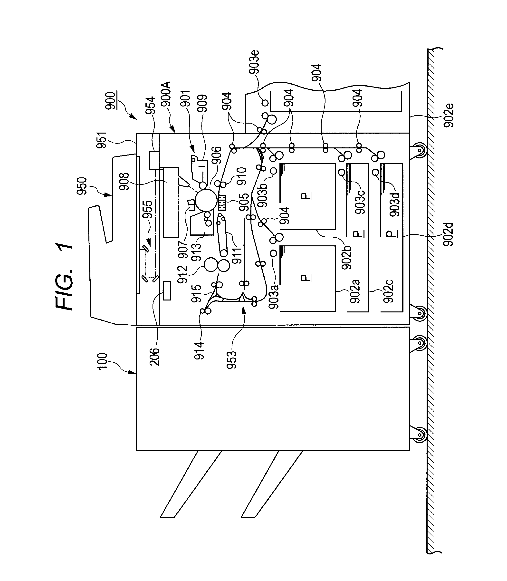
[0027]Now, an embodiment for carrying out the present invention will be described in detail with reference to the drawings. FIG. 1 illustrates a configuration of an image forming apparatus including a sheet processing apparatus having a sheet-discharge apparatus according to the embodiment of the present invention. In FIG. 1, reference numeral 900 denotes an image forming apparatus, and 900A denotes an image forming apparatus body (hereinafter referred to as an apparatus body). The apparatus body 900A includes an image reader (image reading apparatus) 951 including a scanner unit 955 and an image sensor 954, an image forming portion 901 that forms an image on a sheet, and a double-sided apparatus 953, or the like. On an upper surface of the apparatus body 900A, a document feeding apparatus 950 is provided that feeds a document to an unshown platen glass.

[...


PUM


Abstract

The sheet processing apparatus includes a sheet-discharge fan that blows air downward of a sheet-discharged by an upper sheet-discharge roller, and a control portion configured to control an air velocity of air blown from the sheet-discharge fan according to a basic weight of the sheet. In the case where the basic weight of the sheet is a predetermined value or less, the control portion increases the air velocity of the sheet-discharge fan according to the basic weight of the sheet based on basic weight information from an input portion for inputting the basic weight information of the sheet. The control portion also controls the air velocity of the sheet-discharge fan to be a velocity at which the sheet whose rear edge contacts the sheet-stacking wall does not move in a sheet-discharge direction in the case where the basic weight of the sheet exceeds the predetermined value.

Description

BACKGROUND OF THE INVENTION[0001]1. Field of the Invention[0002]The present invention relates to a sheet-discharge apparatus, a sheet processing apparatus, and an image forming apparatus, and more particularly to apparatuses that can discharge a sheet to a sheet-stacking portion while blowing air on a lower surface of the sheet to be discharged, thereby preventing a reduction in sheet alignment properties without reducing productivity.[0003]2. Description of the Related Art[0004]Conventionally, image forming apparatuses such as copiers, laser beam printers, facsimiles, and combination units thereof include a sheet-discharge apparatus that discharges a sheet on which an image is formed onto a stacking tray. Sheet processing apparatuses that process a sheet on which an image is formed also include a sheet-discharge apparatus that discharges a processed sheet onto a stacking tray.[0005]If a leading edge of a sheet that is a downstream edge in a sheet-discharge direction hangs down when...

Claims


Application Information

Patent Timeline
Patent Type & Authority Applications(United States)
IPC IPC(8): G03G15/00B65H31/00
CPCB65H29/14B65H29/245B65H2405/11151B65H2515/112B65H2515/212B65H2801/06G03G2221/1645G03G15/6552B65H2220/01B65H2220/02B65H2515/10B65H2515/20
Inventor OBUCHI, YUSUKE
Owner CANON KK
Why Eureka
Try Eureka