[0023]In the following detailed description of the preferred embodiments, reference is made to the accompanying drawings which form a part hereof, and in which are shown by way of illustration specific embodiments in which the invention may be practiced. In this regard, directional terminology, such as “top,”“bottom,”“front”“back,” etc., is used with reference to the orientation of the Figure(s) being described. The components of the present invention can be positioned in a number of different orientations. As such, the directional terminology is used for purposes of illustration and is in no way limiting. On the other hand, the drawings are only schematic and the sizes of components may be exaggerated for clarity. It is to be understood that other embodiments may be utilized and structural changes may be made without departing from the scope of the present invention. Also, it is to be understood that the phraseology and terminology used herein are for the purpose of description and should not be regarded as limiting. The use of “including,”“comprising,” or “having” and variations thereof herein is meant to encompass the items listed thereafter and equivalents thereof as well as additional items. Unless limited otherwise, the terms “connected,”“coupled,” and “mounted” and variations thereof herein are used broadly and encompass direct and indirect connections, couplings, and mountings. Similarly, the terms “facing,”“faces” and variations thereof herein are used broadly and encompass direct and indirect facing, and “adjacent to” and variations thereof herein are used broadly and encompass directly and indirectly “adjacent to”. Therefore, the description of “A” component facing “B” component herein may contain the situations that “A” component directly faces “B” component or one or more additional components are between “A” component and “B” component. Also, the description of “A” component “adjacent to”“B” component herein may contain the situations that “A” component is directly “adjacent to”“B” component or one or more additional components are between “A” component and “B” component. Accordingly, the drawings and descriptions will be regarded as illustrative in nature and not as restrictive.
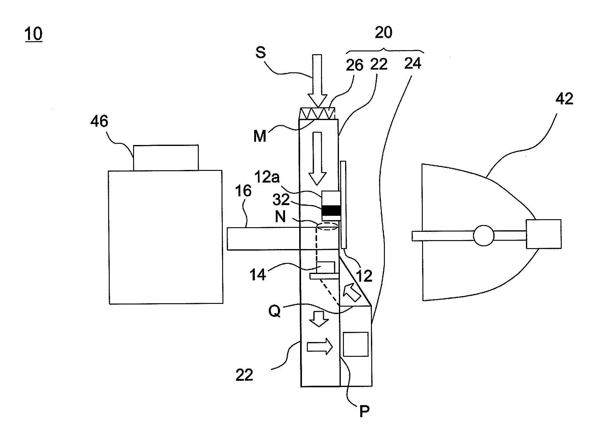
[0024]Please refer to both FIG. 2 and FIG. 3, an optical projection system 10 at least includes a color wheel 12, a photo sensor 14, an integration rod 16, and a heat dissipation module 20. In this embodiment, when the optical projection system 10 operates, a light beam emitted by a light source module 42 passes through the color wheel 12 and the integration rod 16 and then enters a lens module 46. The color wheel 12 has a wheel motor 12a, an index mark 32 is formed on the wheel motor 12a, and the photo sensor 14 is capable of reading the index mark 32.
[0025]More specifically, the heat dissipation module 20 may include a flow channel 22, at least one fan 24, and an air filter 26. The flow channel 22 is disposed in the optical projection system 10 and includes an air intake M and an air vent N. The fan 24 is disposed in the flow channel 22 and has an air inlet P and an air outlet Q. The fan 24 introduces an air flow S and forces the air flow S to enter the flow channel 22 via the air intake M. The air flow S passes through the air inlet P and the air outlet Q of the fan 24 in succession and leaves the flow channel 22 via the air vent N. Further, in this embodiment, the wheel motor 12a is surrounded by the flow channel 22, so noises made by the rotating wheel motor 12a are reduced as a result of the insulation provided by the flow channel 22. Under the circumstance, the overall noises made by the optical projection system 10 are reduced.
[0026]As described above, the color wheel 12 and the photo sensor 14 are disposed in the flow channel 22 and positioned between the air intake M of the flow channel 22 and the air inlet P of the fan 24. The integration rod 16 is disposed in the flow channel 22 and positioned between the air outlet Q of the fan 24 and the air vent N of the flow channel 22. The air filter 26 is disposed in the air intake M of the flow channel 22. According to the above embodiment, when the fan 24 is turned on, the air flow S first passes through the air filter 26 and then flows through and cools down the color wheel 12, the photo sensor 14 and the integration rod 16 in succession. Accordingly, except the color wheel 12, the photo sensor 14 and the integration rod 16 are sufficiently cooled down, the air filter 26 that the air flow S passes through filters dust particles or foreign objects contained in the air flow S beforehand. This prevents the dust particles or the foreign objects brought by the air flow S from being deposited on the index mark 32 and photo sensor 14 to avoid system failure, and prevents the dust particles or the foreign objects from entering the integration rod 16 to avoid a bad influence on the output brightness of the optical projection system.
[0027]Further, in the above design, respective heat endurance for different optical elements are also taken into consideration. For example, since the heat resistance of the color wheel 12 and the photo sensor 14 is relatively lower than the heat resistance of the integration rod 16, the color wheel 12 and the photo sensor 14 are positioned between the air intake M of the flow channel 22 and the air inlet P of the fan 24, and the integration rod 16 is positioned between the air outlet Q of the fan 24 and the air vent N of the flow channel 22. Accordingly, the incoming air flow S with lower temperature passes through the color wheel 12 and the photo sensor 14 first, and then the output air flow S with higher temperature passes through the integration rod 16 to achieve optimized cooling effects.
[0028]Certainly, the heat dissipation module 20 may have various arrangements according to different embodiments. For example, as shown in FIG. 4, in an optical projection system 30 the air filter 26 is disposed in the air intake M of the flow channel 22, an integration rod 16 is positioned between the air intake M of the flow channel 22 and the air inlet P of the fan 24, and the color wheel 12 and the photo sensor 14 are positioned between the air outlet Q of the fan 24 and the air vent N of the flow channel 22. When the fan 24 is turned on, the air flow S passes through the air filter 26 first and then flows through the integration rod 16, the photo sensor 14 and the color wheel 12 to achieve cooling and filtering effects.
[0029]Alternatively, as shown in FIG. 5, a flow channel 22 is disposed in the optical projection system 40 and has an air intake M and an air vent N. A fan 24 is disposed in the air intake M and has an air inlet P and an air outlet Q. In this embodiment, the air intake M of the flow channel 22 serves as the air outlet Q of the fan 24. The fan 24 rotates to induce an air flow S and forces the air flow S to enter the flow channel 22 via the air intake M. A color wheel 12, a photo sensor 14 and an integration rod 16 are disposed in the flow channel 22. The air flow S flows through the color wheel 12, the photo sensor 14 and the integration rod 16 in succession and leaves the flow channel 22 via the air vent N. In this embodiment, the air filter 26 is disposed in the air inlet P of the fan 24, and the air flow S passes through the air filter 26 first as the fan 24 is turned on to achieve cooling and filtering effects.
[0030]In practice, the air filter 26 is able to be disposed near an opening of a bottom cover of a projector. Accordingly, one may open the bottom cover and draw the air filter 26 outside to clean the air filter 26 and the projector.
[0031]The embodiment or the embodiments of the invention may have at least one of the following advantages. According to the above embodiments, when a fan rotates to induce an air flow, the air flow passes through the air filter first and then flows through the color wheel, the photo sensor and the integration rod to achieve cooling effects. Accordingly, except the color wheel, the photo sensor and the integration rod are sufficiently cooled down, the air filter that the air flow passes through first filters the dust particles or the foreign objects contained in the air flow. This prevents the dust particles or the foreign objects brought by the air flow from being deposited on the index mark and the photo sensor to avoid system failure, and prevents the dust particles or the foreign objects from entering the integration rod to avoid a bad influence on the output brightness of the optical projection system. Further, since the wheel motor is surrounded by the flow channel, noises made by the rotating wheel motor are reduced as a result of insulation provided by the flow channel, and the overall noises made by the optical projection system are reduced accordingly.
[0032]The foregoing description of the preferred embodiments of the invention has been presented for purposes of illustration and description. It is not intended to be exhaustive or to limit the invention to the precise form or to exemplary embodiments disclosed. Accordingly, the foregoing description should be regarded as illustrative rather than restrictive. Obviously, many modifications and variations will be apparent to practitioners skilled in this art. The embodiments are chosen and described in order to best explain the principles of the invention and its best mode practical application, thereby to enable persons skilled in the art to understand the invention for various embodiments and with various modifications as are suited to the particular use or implementation contemplated. It is intended that the scope of the invention be defined by the claims appended hereto and their equivalents in which all terms are meant in their broadest reasonable sense unless otherwise indicated. Therefore, the term “the invention”, “the present invention” or the like does not necessarily limit the claim scope to a specific embodiment, and the reference to particularly preferred exemplary embodiments of the invention does not imply a limitation on the invention, and no such limitation is to be inferred. The invention is limited only by the spirit and scope of the appended claims. The abstract of the disclosure is provided to comply with the rules requiring an abstract, which will allow a searcher to quickly ascertain the subject matter of the technical disclosure of any patent issued from this disclosure. It is submitted with the understanding that it will not be used to interpret or limit the scope or meaning of the claims. Any advantages and benefits described may not apply to all embodiments of the invention. It should be appreciated that variations may be made in the embodiments described by persons skilled in the art without departing from the scope of the present invention as defined by the following claims. Moreover, no element and component in the present disclosure is intended to be dedicated to the public regardless of whether the element or component is explicitly recited in the following claims.