Signal line and circuit substrate

a technology of signal lines and circuit substrates, applied in the direction of cross-talk/noise/interference reduction, waveguide devices, waveguide types, etc., can solve the problem of unnecessary radiation from the signal line b>504/b>, and achieve the effect of reducing unnecessary radiation and facilitating inflection of the signal line and the circuit substra

Active Publication Date: 2012-04-26
MURATA MFG CO LTD
View PDF3 Cites 35 Cited by
  • Summary
  • Abstract
  • Description
  • Claims
  • Application Information

AI Technical Summary

Benefits of technology

[0012]According to various preferred embodiments of the present invention, it is possible to easily inflect a signal line and a circuit substrate and it is also possible to reduce unnecessary radiation.

Problems solved by technology

However, the flexible substrate 500 has a problem that unnecessary radiation from the signal line 504 occurs.

Method used


Image

  • Signal line and circuit substrate
  • Signal line and circuit substrate
  • Signal line and circuit substrate

Examples


first preferred embodiment

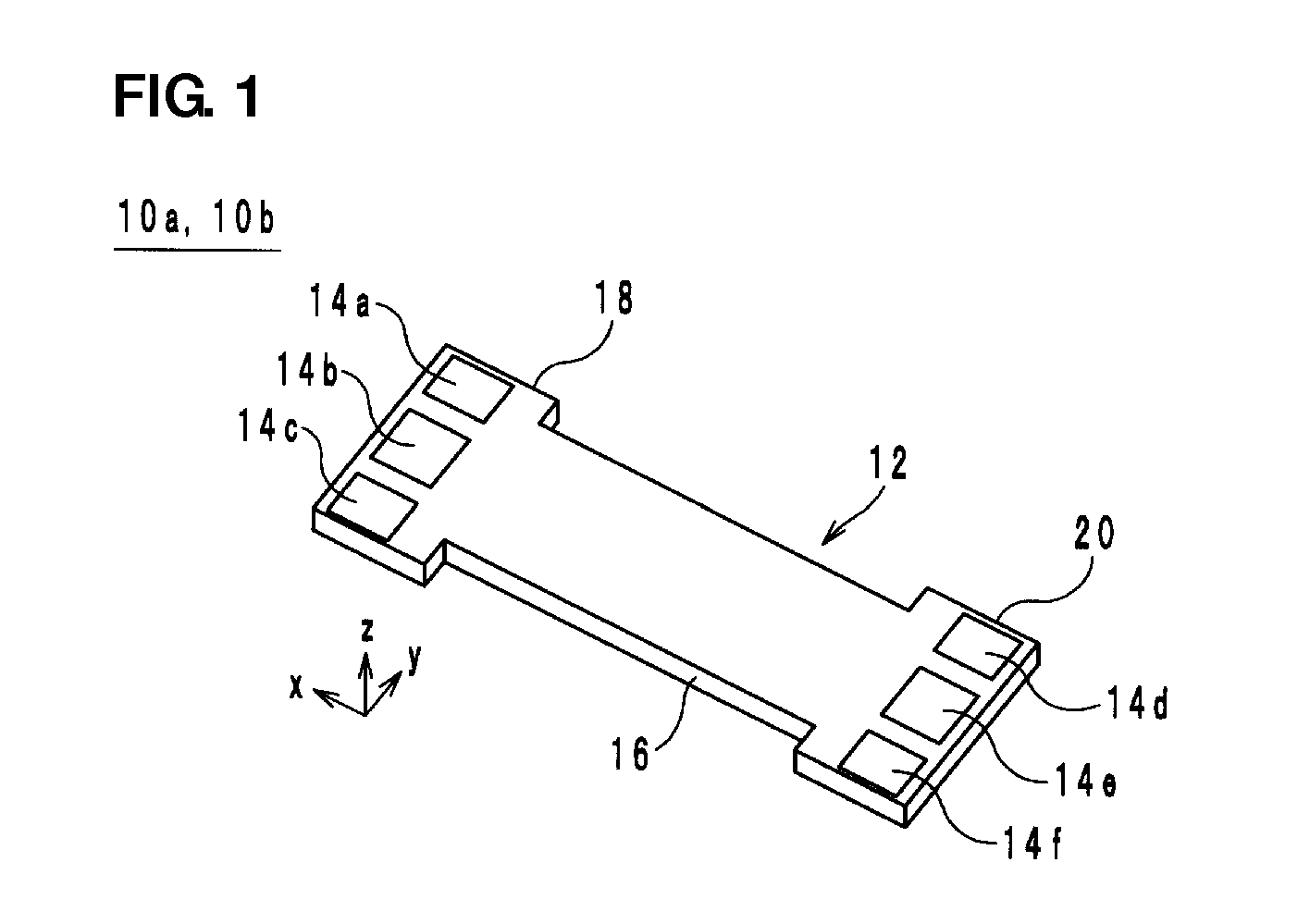
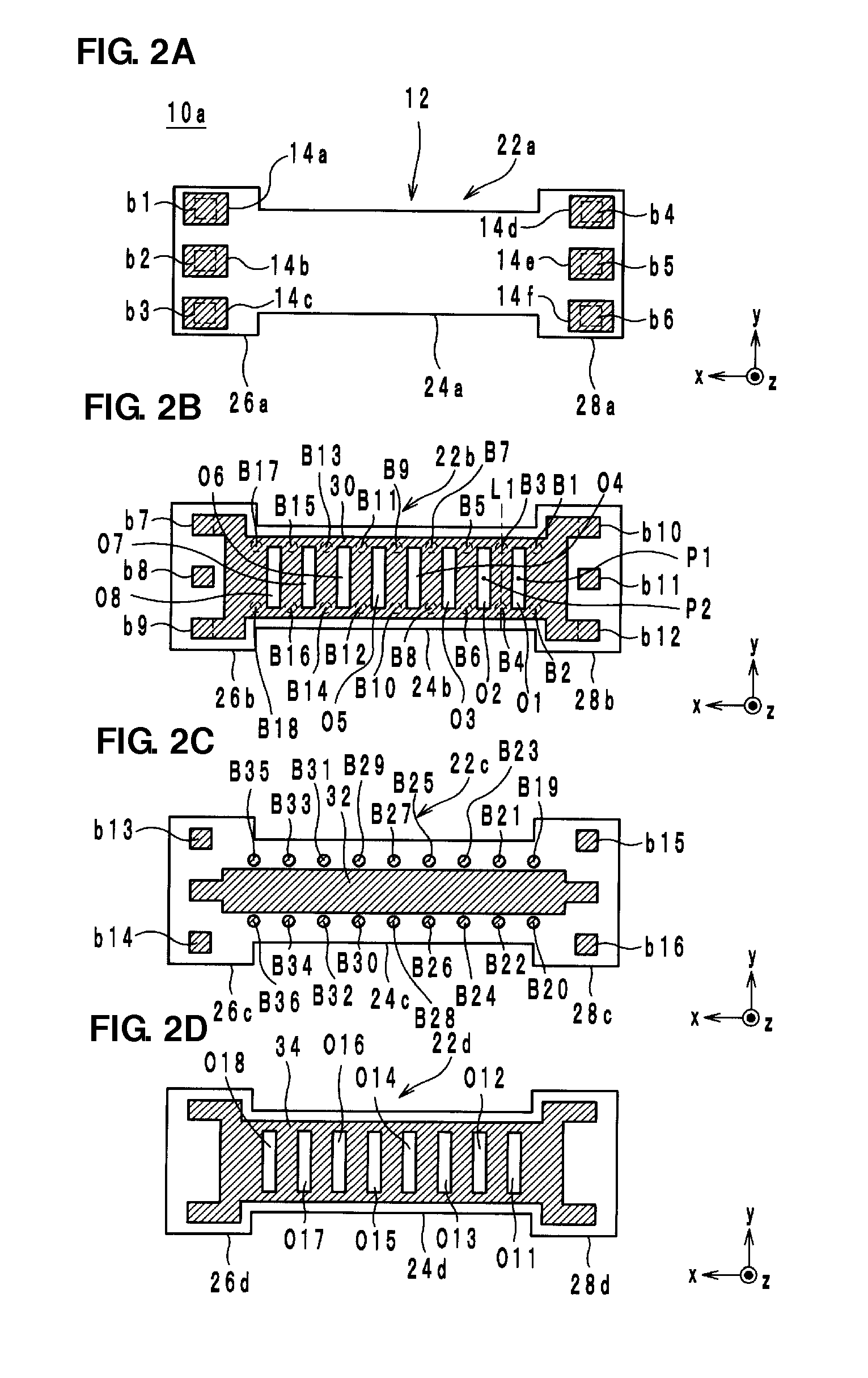
[0020]Hereinafter, the configuration of a signal line according to a first preferred embodiment of the present invention will be described with reference to drawings. FIG. 1 is an external appearance perspective view of a signal line 10a, 10b according to a preferred embodiment of the present invention. FIGS. 2A-2D are exploded views of the signal line10a in FIG. 1. In FIG. 1 and FIGS. 2A-2D, the lamination direction of the signal line 10a is defined as a z axis direction. In addition, the longitudinal direction of the signal line 10a is defined as an x axis direction, and a direction perpendicular to the x axis direction and the z axis direction is defined as a y axis direction, for example.

[0021]For example, the signal line 10a connects two circuit substrates to each other in an electronic device such as a mobile phone or the like. As illustrated in FIG. 1 and FIGS. 2A-2D, the signal line 10a includes a laminated body 12, external terminals 14 (14a to 14f), ground conductors 30 an...


PUM


Abstract

A signal line is a linear conductor provided within a laminated body. A first ground conductor is provided on a positive direction side in a z axis direction within the laminated body, compared with the signal line, and overlaps with the signal line in a planar view seen from the z axis direction. A second ground conductor is provided on a negative direction side in the z axis direction within the laminated body, compared with the signal line, and overlaps with the signal line in the planar view seen from the z axis direction. Via hole conductors connect the ground conductors to each other. In the first ground conductor, a plurality of opening portions are arranged along the signal line in the planar view seen from the z axis direction. The via hole conductors are provided between the opening portions adjacent to one another, in an x axis direction.

Description

BACKGROUND OF THE INVENTION[0001]1. Field of the Invention[0002]The present invention relates to a signal line and the circuit substrate thereof, and, more specifically, relates to a signal line that is capable of being easily inflected and reducing unnecessary radiation, and a circuit substrate thereof.[0003]2. Description of the Related Art[0004]As a signal line of the related art, for example, a flexible substrate described in Japanese Unexamined Patent Application Publication No. 2007-123740 is known. FIGS. 5A and 5B are cross-section structure diagrams of a flexible substrate 500 described in Japanese Unexamined Patent Application Publication No. 2007-123740.[0005]A cross-section structure illustrated in FIG. 5A and a cross-section structure illustrated in FIG. 5B are alternately disposed, and hence the flexible substrate 500 is configured. More specifically, the flexible substrate 500 includes insulation layers 502a to 502d, a signal line 504 and ground layers 506a and 506b. I...

Claims


Application Information

Patent Timeline
Patent Type & Authority Applications(United States)
IPC IPC(8): H05K1/02
CPCH01P3/081H01P3/088H05K1/0219H05K1/0298H05K1/028H05K2201/0715H05K2201/09618H05K1/0225H01P3/08H05K3/46
Inventor KATO, NOBORUSASAKI, JUNISHINO, SATOSHI
Owner MURATA MFG CO LTD
Why Eureka
Try Eureka