Countermeasure arrangement

a countermeasure and arrangement technology, applied in the direction of launching weapons, refracting targets, transportation and packaging, etc., can solve the problems of substantial limitation of the amount of countermeasures in the form of aluminized foil, fibers and chaffs carried by aircraft, and achieve effective countermeasure arrangement, reduce costs, and increase the effect of countermeasure payload

Active Publication Date: 2012-04-26
SAAB AB
View PDF12 Cites 9 Cited by
  • Summary
  • Abstract
  • Description
  • Claims
  • Application Information

AI Technical Summary

Benefits of technology

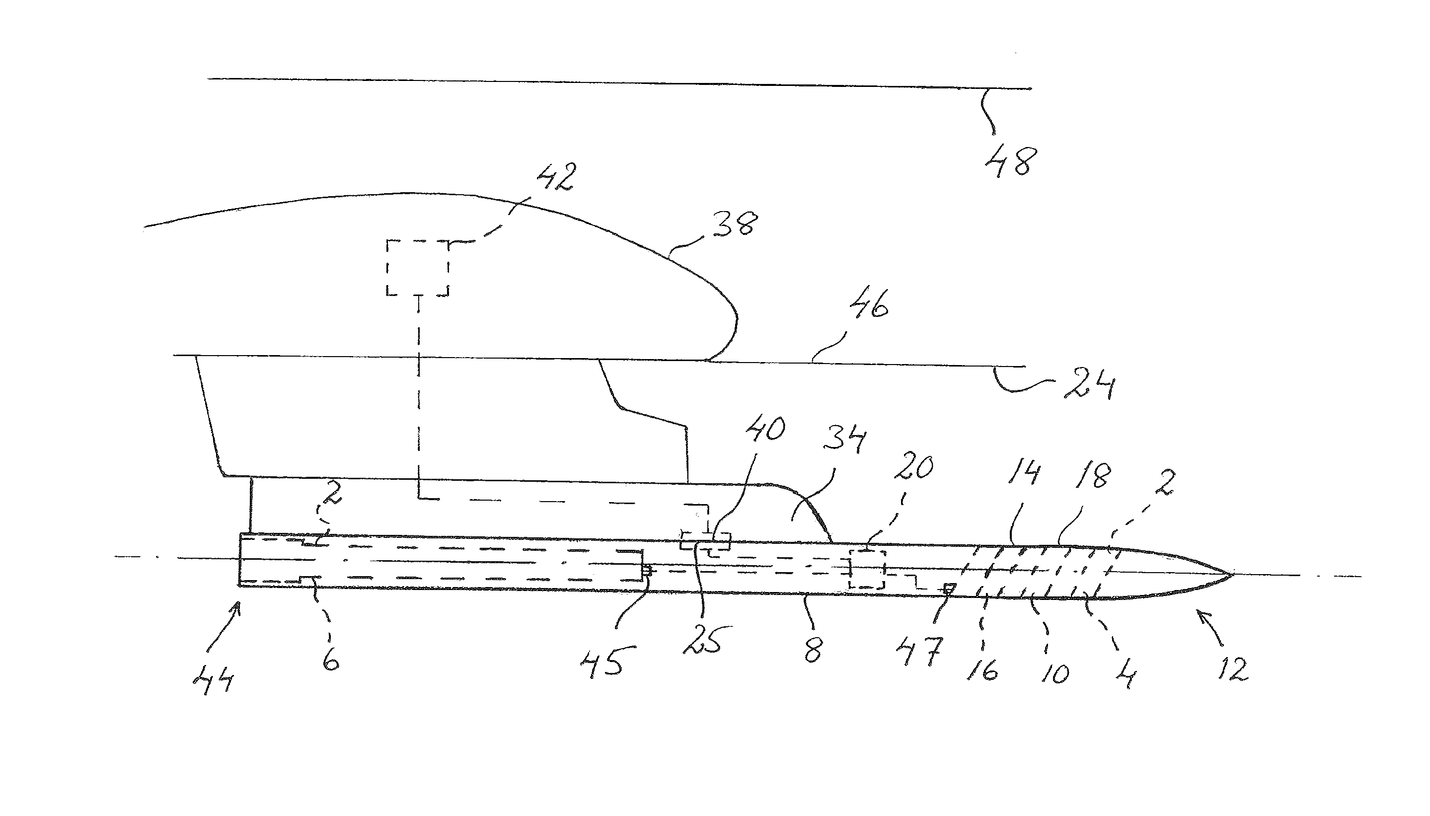
[0013]The first electrical terminals are adapted to mate with second electrical terminals on the hard point on the aircraft. When electrical terminals mate a trouble-free transmission of power and control signals between the aircraft and the arrangement according to the present invention is possible.
[0014]The first control means is adapted to communicate with second control means on the aircraft. The first control means of the arrangement according to the present invention can communicate with second control means on the aircraft without reconstructing the second control system on the aircraft. This decreases costs for arranging the arrangement according to the present invention on the aircraft.
[0015]The envelope has a form and a design which substantially correspond to a form and a d

Problems solved by technology

The amount of countermeasures in the form of aluminized foil, fibers and chaffs carried by aircraft is substantially l

Method used


Image

  • Countermeasure arrangement
  • Countermeasure arrangement
  • Countermeasure arrangement

Examples


first embodiment

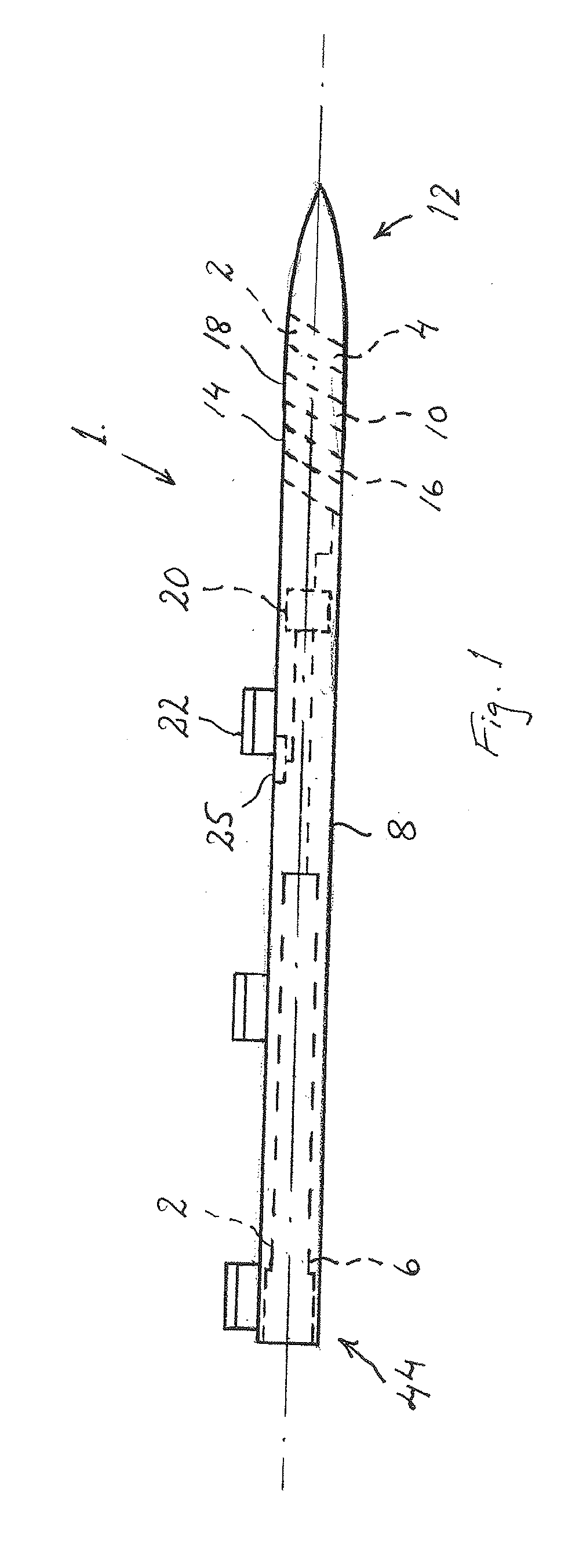
[0030]FIG. 1 shows a side view of a countermeasure arrangement 1 according to the present invention. The countermeasure arrangement 1 is provided with a countermeasure dispenser 2, which comprises a first countermeasure dispenser unit 4 and second countermeasure dispenser unit 6. The first and second countermeasure dispenser units 4, 6 are at least partly enclosed by an envelope 8 having an elongated outer form and a substantially circular cross section designed to minimize the air drag.

[0031]Openings for dispensing countermeasures 10 from the first and second countermeasure dispenser units 4, 6 are arranged in the envelope 8. At the front part 12 of the envelope 8 there is a front opening 14 at the first countermeasure dispenser unit 4, which comprises a compartment section with a number of compartments 16, intended to accommodate countermeasures in the form of preferably propelled or un-propelled flares or countermeasure 10. The countermeasures are preferably accommodated in cartr...

second embodiment

[0038]FIG. 4 shows a view in perspective of a countermeasure arrangement 1 according to the present invention. The envelope 8 is pivotable at least partly about a longitudinal axis of the envelope 8. The direction of dispensing the countermeasures may be adjusted in relation to the specific aircraft 24 the countermeasure arrangement 1 is installed to. Preferably, the countermeasure dispenser 2 is arranged in that part of the envelope 8 that is pivotable, so that countermeasures may be dispensed in different directions in relation to an aircraft 24 on which the arrangement is arranged. This will increase the flexibility and the efficiency of the countermeasure arrangement 1. In the embodiment according to FIG. 3 the front part 12 of the envelope, in which the first countermeasure dispenser unit 4 is installed, is pivotable about the longitudinal axis of the envelope 8. Thus, when pivoting the front part 12 of the envelope 8 the direction of the front opening 14 for dispensing counter...


PUM


Abstract

A countermeasure arrangement including a countermeasure dispenser. An envelope at least partly encloses the countermeasure dispenser. A first control module is configured to control the countermeasure dispenser. A suspension module is arranged on the envelope for suspending the envelope on an aircraft. The suspension module has a form and a design that substantially correspond to the form and design of a suspension rail of a missile, so that the suspension module mates to a hard point on the aircraft, which is adapted to the missile.

Description

TECHNICAL FIELD[0001]The present invention relates to a countermeasure arrangement according to the preamble of claim 1.BACKGROUND ART[0002]Dispenser units arranged to dispense countermeasures from aircrafts are well known. Both fighter and transport aircrafts, as well as civil aircrafts are exposed for threats from self-guided missiles equipped with radar, IR or laser sensors, which can be fired either from other aircrafts or from the ground. In order to protect the threatened aircrafts from an attack of such missiles they are provided with various types of dispenser units which dispense countermeasure means. Such countermeasure means may comprise aluminized foil or fibers, pyrophoric IR materials, flares and also laser-reflecting fibers or foils, which confuse and divert missiles aimed at the aircraft.[0003]The amount of countermeasures in the form of aluminized foil, fibers and chaffs carried by aircraft is substantially limited due to the great number of different weapons, senso...

Claims


Application Information

Patent Timeline
IPC IPC(8): F41H11/02B64D1/02
CPCB64D7/08F42B12/70F41J2/02F41F3/065
Inventor ZATTERQVIST, CHRISTER
Owner SAAB AB
Why Eureka
Try Eureka