Portable wireless terminal
a wireless terminal and portability technology, applied in the field of portability wireless terminals, can solve the problems of radiation gain decline, loss of matching state of the antenna, etc., and achieve the effect of preventing the degradation of the antenna performance, increasing the number of components, and sacrificing the design
- Summary
- Abstract
- Description
- Claims
- Application Information
AI Technical Summary
Benefits of technology
Problems solved by technology
Method used
Image

Examples
embodiment 1
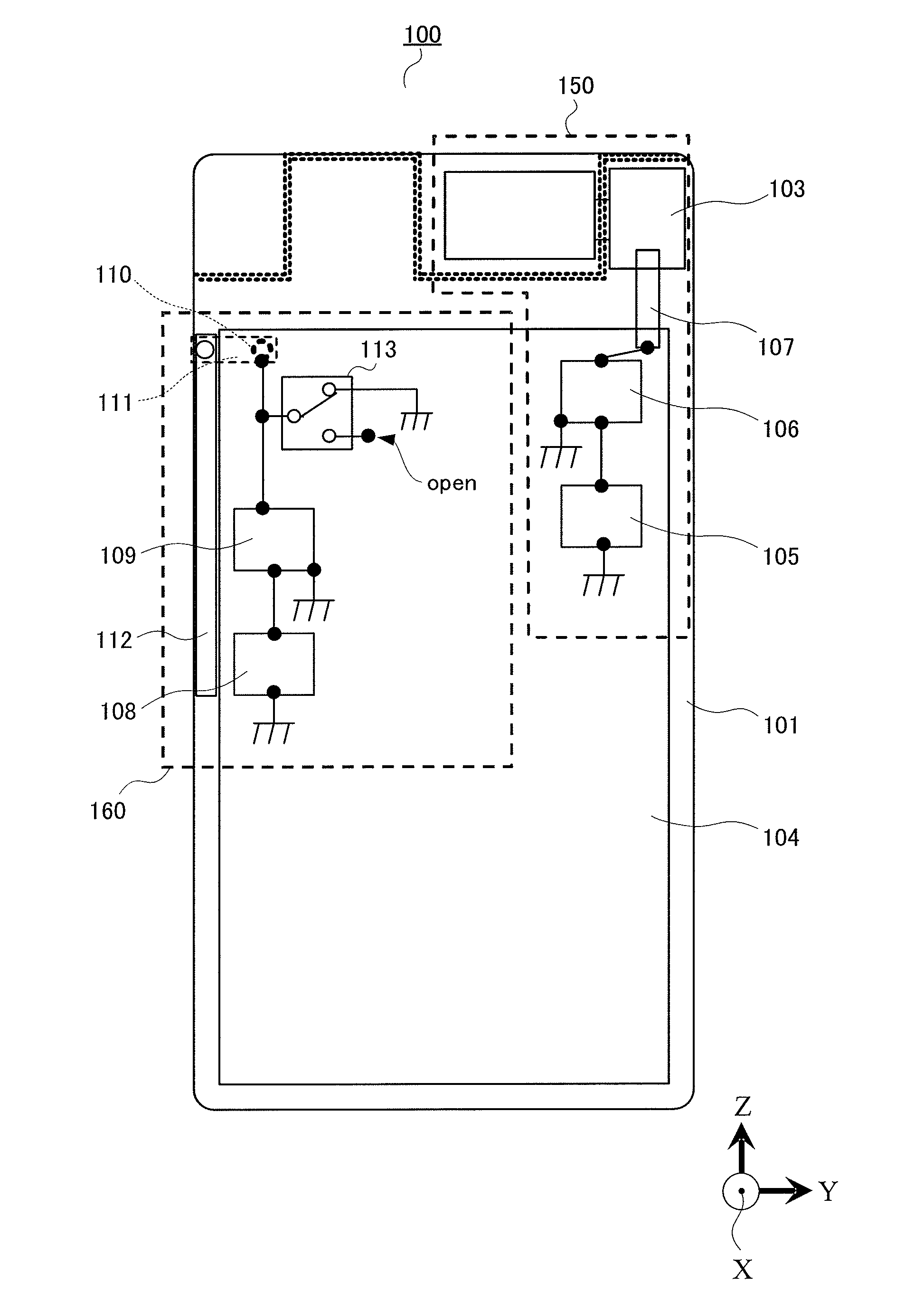
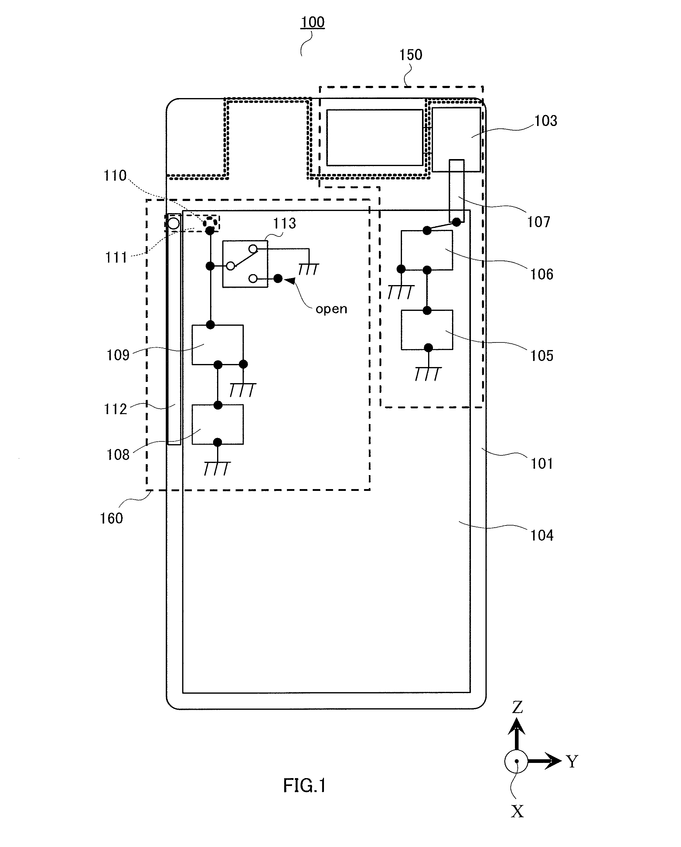
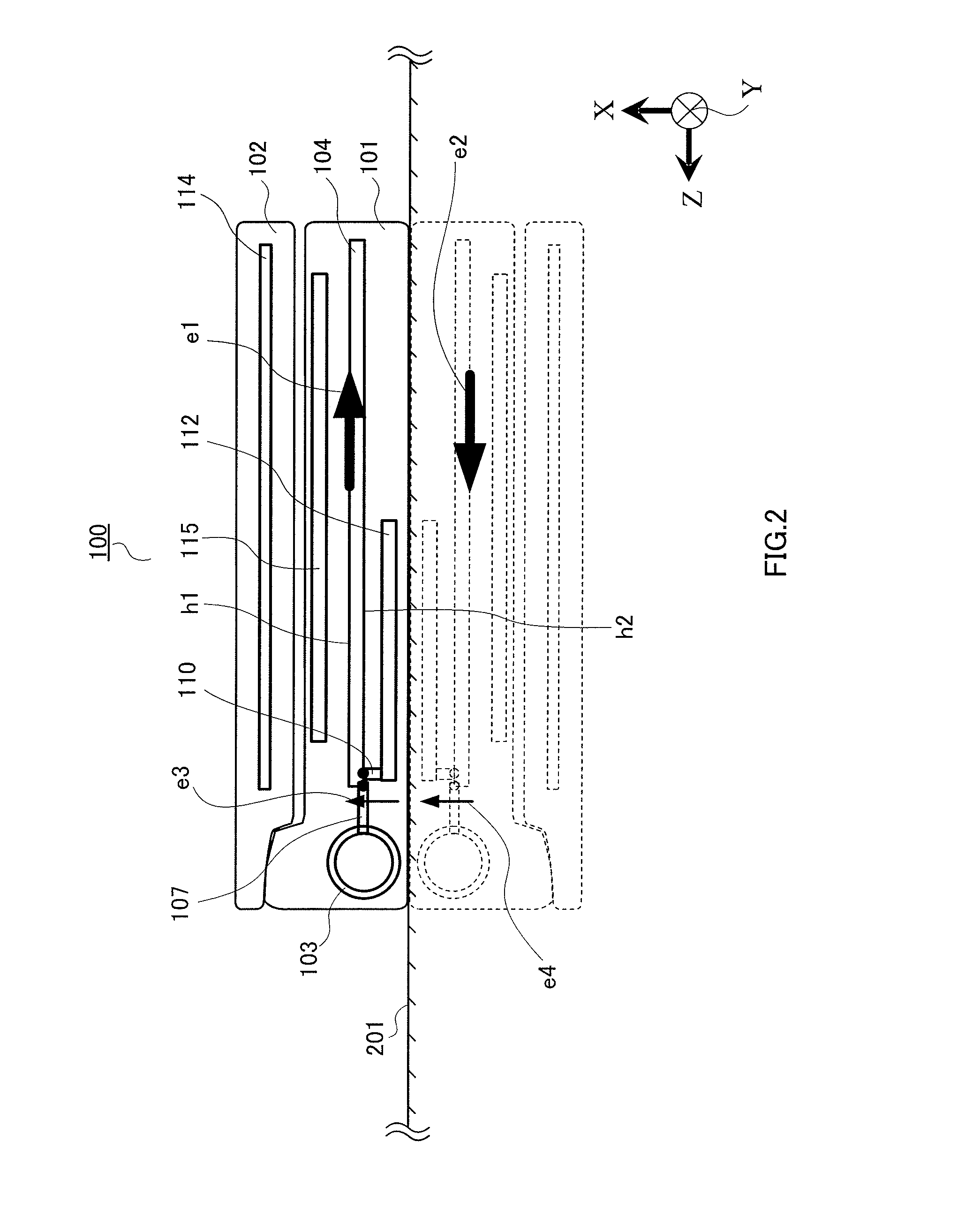
[0021]FIG. 1 is a plan view illustrating an essential portion of portable wireless terminal 100 according to Embodiment 1 of the present invention. FIG. 2 is a side view illustrating portable wireless terminal 100 according to Embodiment 1 of the present invention when portable wireless terminal 100 is closed.
[0022]Portable wireless terminal 100 includes first casing 101, second casing 102, hinge section 103, first circuit substrate 104, first wireless circuit 105, first matching circuit 106, first contact spring 107, second wireless circuit 108, second matching circuit 109, second contact spring 110, coupling section 111, whip antenna 112, switch 113, second circuit substrate 114, and input device 115. First wireless system 150 is constituted by first wireless circuit 105, first matching circuit 106, first contact spring 107, and metal rotation shaft 116. Second wireless system 160 is constituted by second wireless circuit 108, second matching circuit 109, second contact spring 110...
embodiment 2
[0046]FIG. 3 is a plan view illustrating an essential portion of portable wireless terminal 300 according to Embodiment 2 of the present invention.
[0047]Portable wireless terminal 300 shown in FIG. 3 includes reactance circuit 301 in addition to portable wireless terminal 100 according to Embodiment 1 shown in FIG. 1. In FIG. 3, portions having the same configurations as those of FIG. 1 are denoted with the same reference numerals, and description there about is omitted. The side view of portable wireless terminal 300 is the same as that of FIG. 2 except that portable wireless terminal 300 has reactance circuit 301, and therefore, description thereabout is omitted.
[0048]Portable wireless terminal 300 includes first casing 101, second casing 102, hinge section 103, first circuit substrate 104, first wireless circuit 105, first matching circuit 106, first contact spring 107, second wireless circuit 108, second matching circuit 109, second contact spring 110, coupling section 111, whip...
embodiment 3
[0055]FIG. 4 is a plan view illustrating an essential portion of portable wireless terminal 400 according to Embodiment 3 of the present invention.
[0056]Portable wireless terminal 400 as shown in FIG. 4 is different from portable wireless terminal 100 according to Embodiment 1 as shown in FIG. 1 in that portable wireless terminal 400 does not have switch 113 but additionally includes first trap circuit 401, second trap circuit 402, and reactance circuit 403. In FIG. 4, portions having the same configurations as those of FIG. 1 are denoted with the same reference numerals, and description there about is omitted. The side view of portable wireless terminal 400 is the same as that of FIG. 2 except that portable wireless terminal 400 has first trap circuit 401, second trap circuit 402, and reactance circuit 403, and therefore, description thereabout is omitted.
[0057]Portable wireless terminal 400 includes first casing 101, second casing 102, hinge section 103, first circuit substrate 10...
PUM
 Abstract
Description
Claims
Application Information
 - R&D
- Intellectual Property
- Life Sciences
- Materials
- Tech Scout
- Unparalleled Data Quality
- Higher Quality Content
- 60% Fewer Hallucinations
Browse by: Latest US Patents, China's latest patents, Technical Efficacy Thesaurus, Application Domain, Technology Topic, Popular Technical Reports.
© 2025 PatSnap. All rights reserved.Legal|Privacy policy|Modern Slavery Act Transparency Statement|Sitemap|About US| Contact US: help@patsnap.com