Video collaboration type illuminating control system and video collaboration type illuminating control method

a technology of illuminating control system and video collaboration, which is applied in the direction of television system, process and machine control, etc., can solve the problems of inability to accurately reproduce the state of light in the vicinity of the display, small screen area may have too small effect to properly perform lighting device setup, etc., and achieve the effect of more realism

Inactive Publication Date: 2012-04-26
PANASONIC CORP
View PDF5 Cites 21 Cited by
  • Summary
  • Abstract
  • Description
  • Claims
  • Application Information

AI Technical Summary

Benefits of technology

[0013]In view of the conventional problems, it is an object of the present invention to provide a video link type illuminating control system and a video link ty...

Problems solved by technology

In some video being displayed, however, it is difficult to faithfully reproduce the state of light in the vicinity of the display only by the information of the video being displayed on the screen.
For example, when there is an object in a dark space, and the object is displayed to fit the screen size, the surrounding area of the display should be dark, but it is actually illuminated with the color of the object, possibly resulting in being less realistic.
Actually, however, an extremely small area of the screen may have too small an effect to properly perform the setup of the lighting devices.
Thus, in Patent Literature 1 as a conventional example, the setup of...

Method used


Image

  • Video collaboration type illuminating control system and video collaboration type illuminating control method
  • Video collaboration type illuminating control system and video collaboration type illuminating control method
  • Video collaboration type illuminating control system and video collaboration type illuminating control method

Examples


first exemplary embodiment

[0055]A first exemplary embodiment according to the present invention will be described as follows with reference to FIGS. 1 to 5.

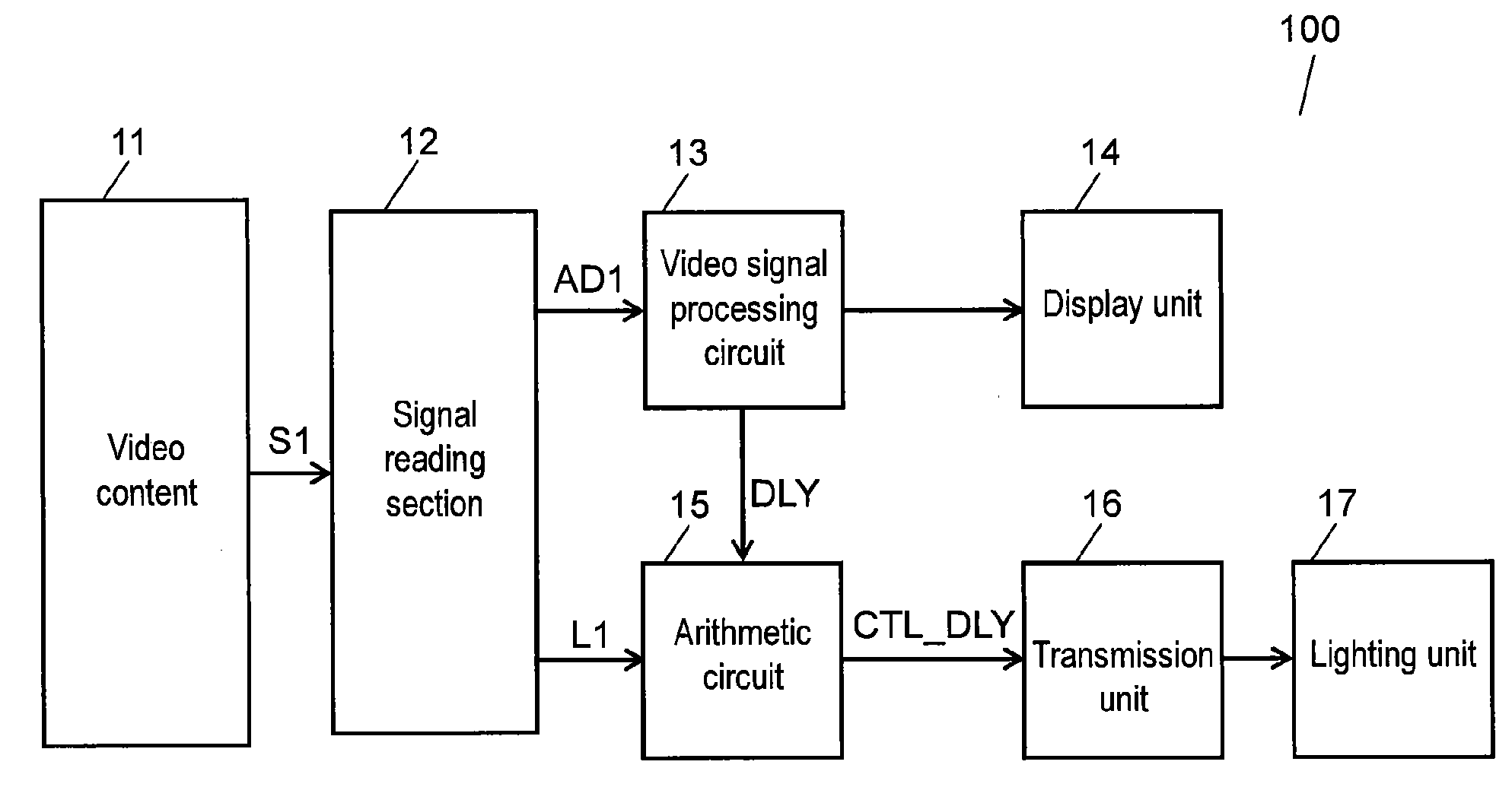
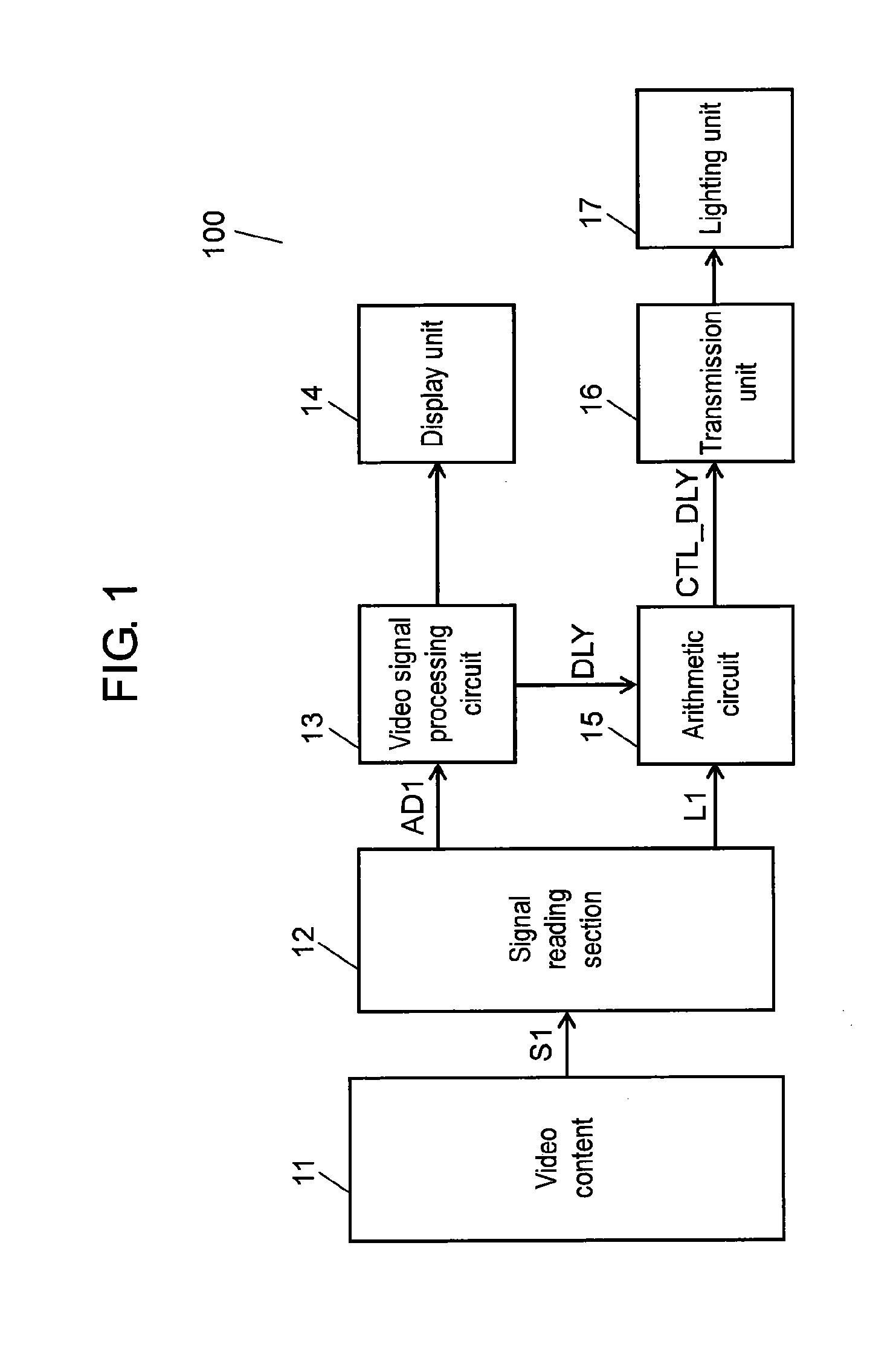
[0056]FIG. 1 is a block diagram of a video link type illuminating control system according to the present invention. In FIG. 1, video link type illuminating control system 100 includes video content 11, signal reading section 12, video signal processing circuit 13, display unit 14, arithmetic circuit 15, transmission unit 16, and lighting unit 17.

[0057]Video content 11 includes, in addition to a video signal and an audio signal that are conventionally included in a video content, an optical information signal indicating the position and the intensity of a light source for illuminating audio-visual space. Video content 11 can be received from a broadcast channel or a network, or reproduced from a storage medium or memory.

[0058]Signal reading section 12 reads signal S1 from video content 11, and provides video signal processing unit 13 with video signal AD1...

second exemplary embodiment

[0073]A second exemplary embodiment will describe the structure of the first exemplary embodiment in greater detail. The second exemplary embodiment is compliant with the HDMI standard, but the present invention is not limited to this standard. The second exemplary embodiment shows an example in which HDMI Source 600 transmits a video signal and a control signal to HDMI Sink 650 via HDMI 680, and then HDMI Sink 650 transmits the control signal (optical information signal) to the above-mentioned lighting unit. HDMI Source 600 can be a STB (Set Top Box), and HDMI Sink 650 can be a TV (television receiver). The present invention, however, is not limited to this: HDMI Source 600 can be replaced by video and control signals, which can be received from a broadcasting station either wired or wirelessly, recorded in a storage medium or memory, or obtained from a network.

[0074]A structure to achieve the present invention will be described as follows with reference to FIGS. 6 to 8. FIGS. 6 an...

third exemplary embodiment

[0088]A third exemplary embodiment of the present invention will be described as follows with reference to FIGS. 9 and 10. FIG. 9 is a block diagram of a video link type illuminating control system according to the third exemplary embodiment.

[0089]In FIG. 9, video link type illuminating control system 900 includes video content 911, signal reading section 912, video signal processing circuit 913, display control unit 921, display unit 914, arithmetic circuit 915, transmission unit 916, lighting unit 917, optical sensor 922, and outside light 923. Video content 911, signal reading section 912, video signal processing circuit 913, display unit 914, arithmetic circuit 915, transmission unit 916, and lighting unit 917 are identical to video content 11, signal reading section 12, video signal processing circuit 13, display unit 14, arithmetic circuit 15, transmission unit 16, and lighting unit 17, respectively, shown in FIGS. 1 and 2, and hence the description thereof will be omitted. Sy...


PUM


Abstract

A video link type illuminating control system and video link type illuminating control method allow a signal containing the idea of the content creator to be added to an airwave signal or a video content signal so that the audio-visual space is illuminated based on the control signal generated from the signal. As a result, illumination can be controlled in linkage with video, thus increasing visual realism.

Description

TECHNICAL FIELD[0001]The present invention relates to a video link type illuminating control system and a video link type illuminating control method which control the lighting equipment arranged around the viewer according to the video being displayed, thereby delivering a greater sense of realism.BACKGROUND ART[0002]New technologies have been developed in recent years to increase a sense of realism when viewing video such as TV shows and movies. In terms of audio quality in particular, a multi-channel surround system such as a 5.1 channel surround system allows the viewer to enjoy highly realistic video and audio at home.[0003]In terms of video quality, on the other hand, various suggestions have been made to provide a sense of expanse when viewing the video. This is achieved by analyzing the colors of the video to be displayed and controlling the lighting equipment that illuminates the vicinity of the display. Patent Literature 1 below, for example, suggests providing a sense of ...

Claims


Application Information

Patent Timeline
IPC IPC(8): H04N5/57H05B37/02H04N7/18
CPCH05B37/0254H05B37/02H05B47/18H05B47/165
Inventor FUJINO, TOSHIHIROISHIKAWA, YUICHISAITO, NATSUKI
Owner PANASONIC CORP
Why Eureka
Try Eureka