Devices and methods providing for intra-die cooling structure reservoirs

Inactive Publication Date: 2012-04-26
COOLSILICON
View PDF15 Cites 2 Cited by
  • Summary
  • Abstract
  • Description
  • Claims
  • Application Information

AI Technical Summary

Benefits of technology

[0015]In another example, an integrated circuit (IC) device is described herein. The IC device includes a plurality of layers. The IC device further includes means for housing a fluid for the thermal management of the IC device integral to at least one of the plurality of integral layers. The IC

Problems solved by technology

This generated heat may cause a variety of operational and/or structural issues.
In addition, a “hot” IC may suffer from data and other reliability issues, and may consume more power than a device operating at lower temperatures.
The IC may even fail functionally or physically.
Because multi-substrate IC devices incorporate

Method used


Image

  • Devices and methods providing for intra-die cooling structure reservoirs
  • Devices and methods providing for intra-die cooling structure reservoirs
  • Devices and methods providing for intra-die cooling structure reservoirs

Examples


Embodiment Construction

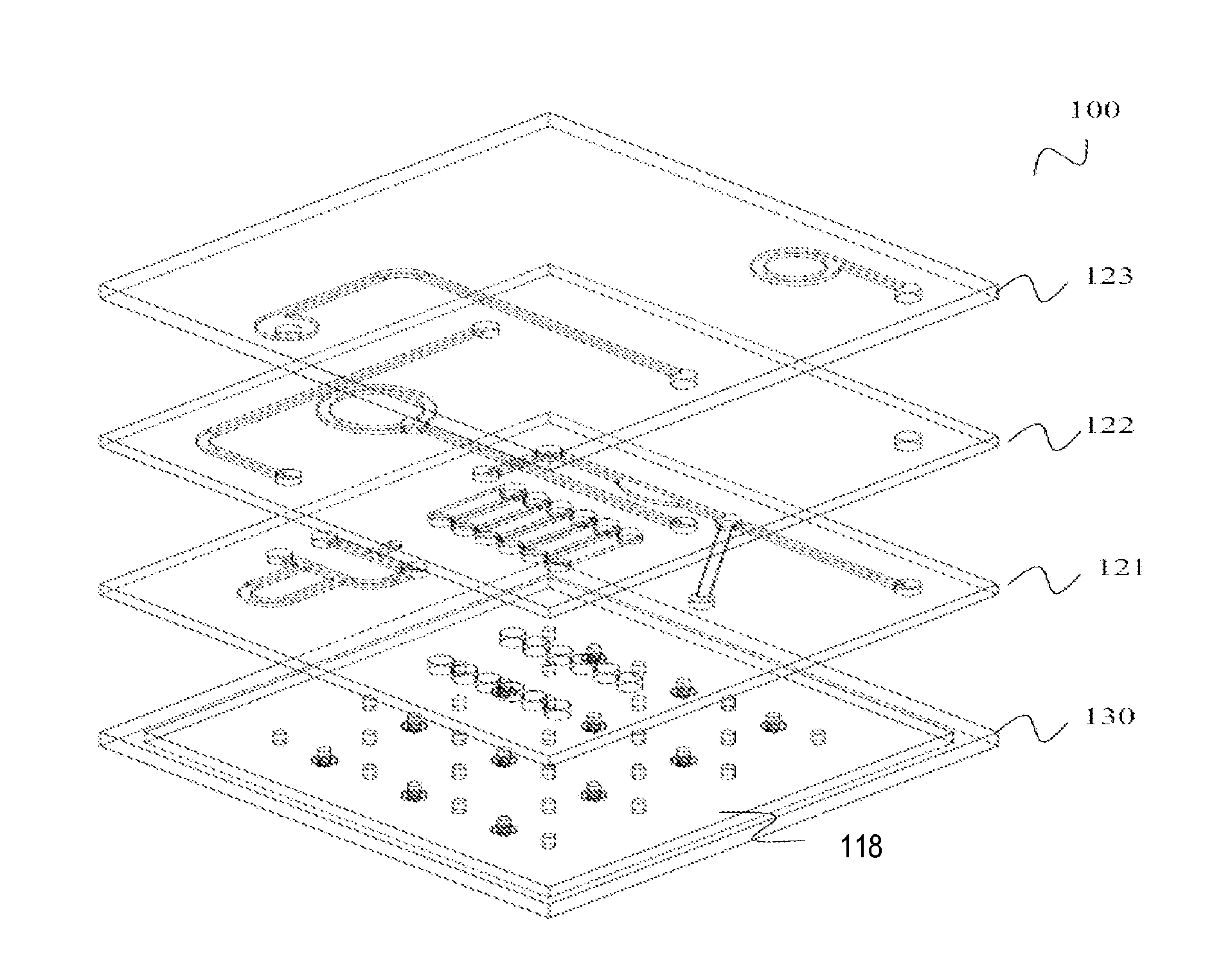
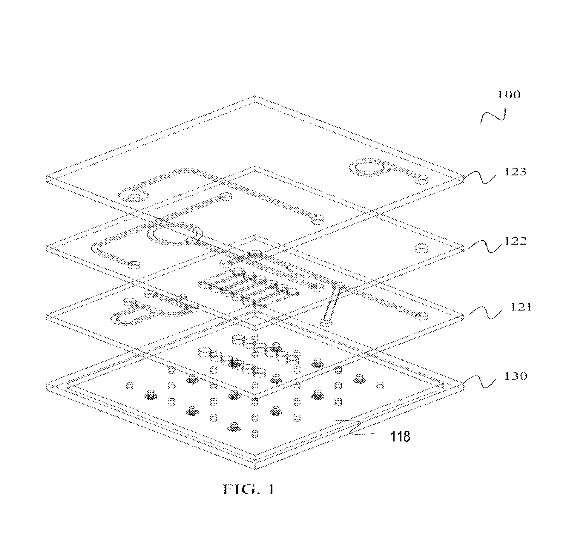
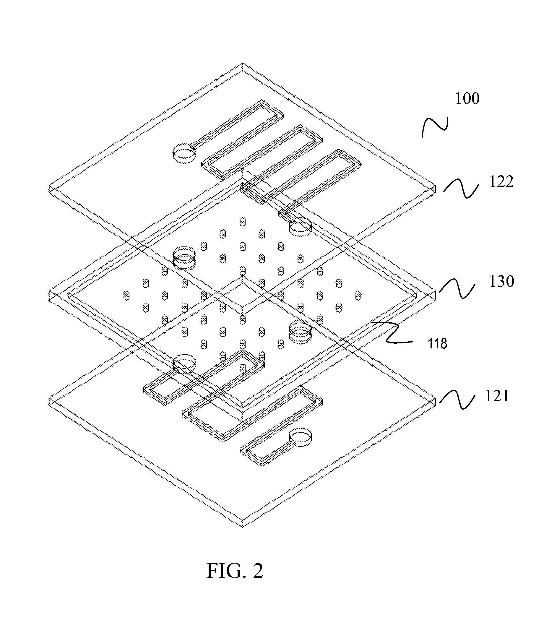
[0028]FIG. 1 illustrates generally one embodiment of an IC die 100 that includes an intra-die cooling structure according to various aspects of the invention described herein. As shown in FIG. 1, the intra-die cooling structure includes various intra and inter-layer cooling channels defined in integral layers 121-123 of semiconductor die 100. Layers of die 100 as described herein may be considered integral in the sense that they are adjacent layers of a single die 100. In various embodiments, layers 121-123 of die 100 may be any combination of device layers, metallization / via, routing, or power layers, or any other layers that may be part of an IC device comprising IC die 100. The channels may be fluidically coupled to a reservoir 118 defined in integral layer 130. Layer 130 may be formed integral to one or more other layers of die 100, e.g., layer 121 in the example of FIG. 1. In other embodiments, as shown in FIG. 2, reservoir 118 may be defined in between other integral layers 12...


PUM


Abstract

Devices, systems, and methods for semiconductor die temperature management are described and discussed herein. An IC device is described that includes at least one intra-die cooling structure. In an embodiment, the IC device includes at least one coolant reservoir and at least one coolant channel disposed wholly within integral layers of the semiconductor die. The at least one coolant reservoir includes at least one through-reservoir via. The at least one through-reservoir via may be constructed to provide structural support to the at least one coolant reservoir. The at least one through-reservoir via may also be constructed to provide a path for the transfer of thermal energy, electrical signals, and/or power signals. The at least one through-reservoir via may be constructed to provide any combination of structural support and thermal energy transfer, electrical signal transfer, or power transfer.

Description


Claims


Application Information

Patent Timeline
Owner COOLSILICON
Why Eureka
Try Eureka