Fan structure

Inactive Publication Date: 2012-04-26
ZAWARD CORP
View PDF11 Cites 6 Cited by
  • Summary
  • Abstract
  • Description
  • Claims
  • Application Information

AI Technical Summary

Benefits of technology

[0012]In comparison with prior art, the fan structure of the present invention is provided on the blade with a plurality of polygonal dents. When the airflow passes through the surface of each blade, the airflow is brought into contact with the periphery of each polygonal dent to generate a turbulent flow. The turbulent flow stays in the polygonal dent. A plurality of the turbulent flows collect together to form an air film for separating

Problems solved by technology

On the other hand, if the noise generated by the heat-dissipating fan is too large, the user will feel very uncomfortable.
The turbulent flows may cause the blades to vibrate and thus generate

Method used


Image

  • Fan structure
  • Fan structure
  • Fan structure

Examples


Embodiment Construction

[0019]The detailed description and technical contents of the present invention will become apparent with the following detailed description accompanied with related drawings. It is noteworthy to point out that the drawings is provided for the illustration purpose only, but not intended for limiting the scope of the present invention.

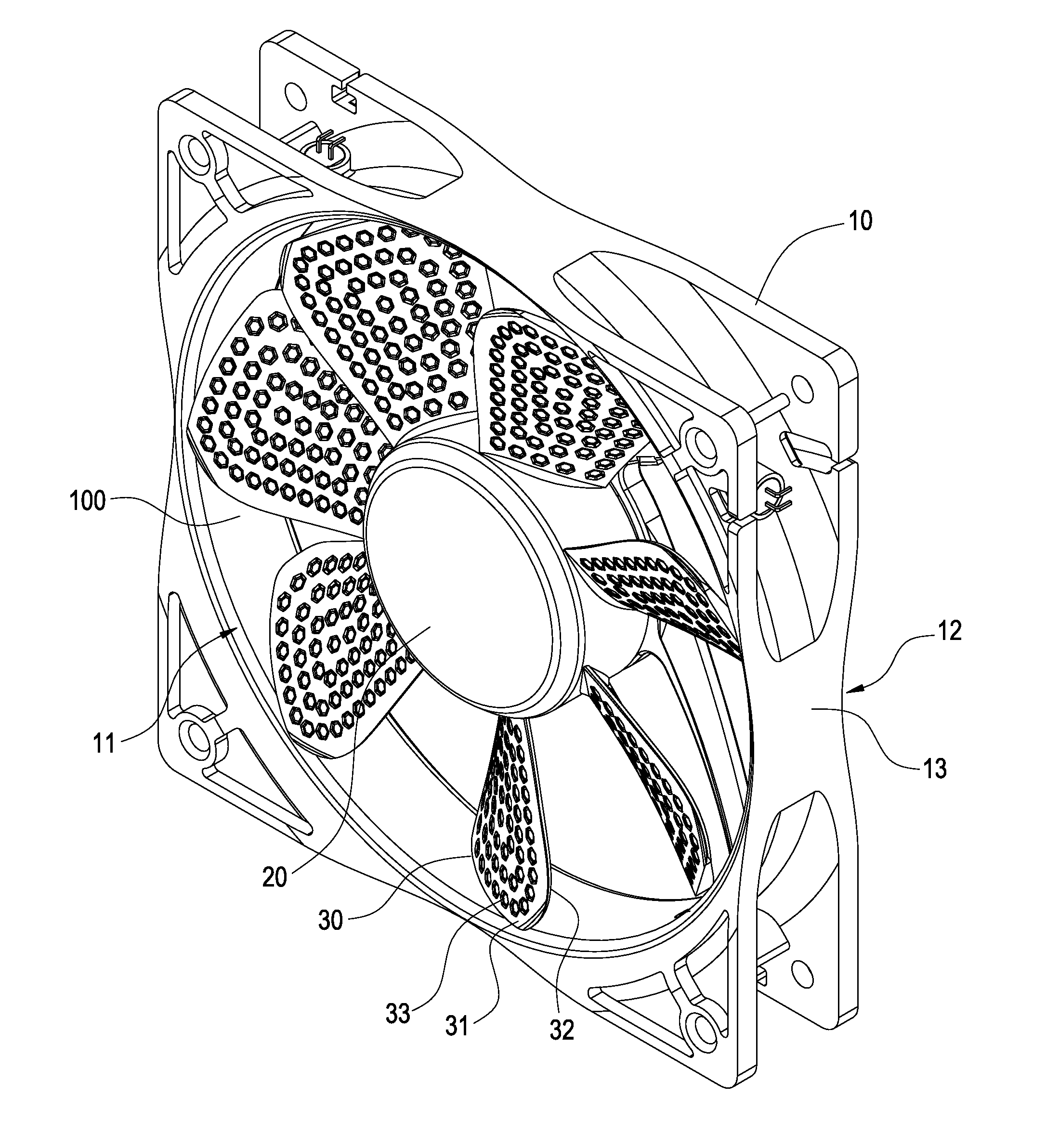
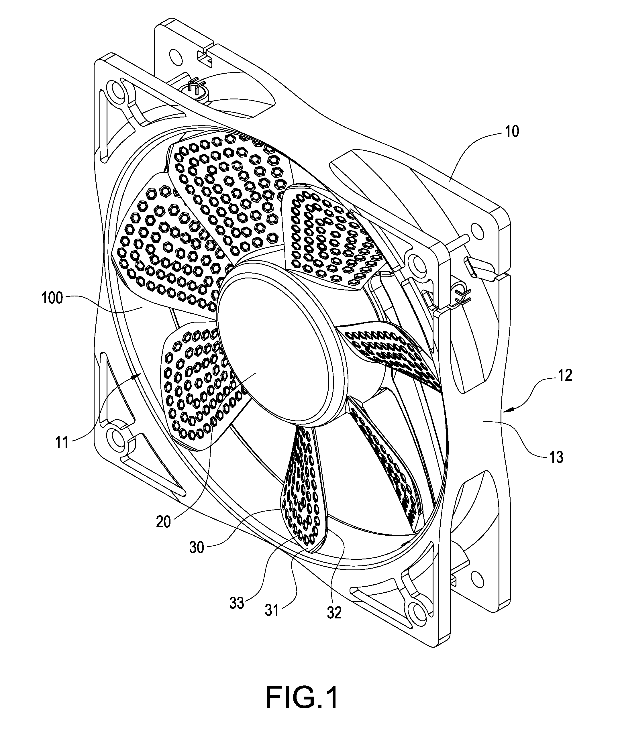
[0020]Please refer to FIGS. 1 to 3. The present invention provides a fan 1, which includes a casing 10, a hub 20 and a plurality of blades 30 extending from the periphery of the hub 20.

[0021]The casing 10 is formed into a square frame and has an accommodating space 100 therein. The hub 20 and the plurality of blades 30 are combined in the accommodating space 100. The casing 10 comprises an intake side 11 and an exhaust side 12 opposite to the intake side 11. The peripheries of the intake side 11 and the exhaust side 12 are formed with a recessed portion 13 respectively which is recessed toward the accommodating space 100. In the present embodiment, four ...


PUM


Abstract

A fan structure includes a hub and a plurality of blades extending from the periphery of the hub. The airflow generated by the fan forms a boundary layer on the surface of each blade. The present invention is characterized in that: each of the blades is provided with a plurality of polygonal dents, a turbulent flow is generated in each dent when the airflow passes through the dent, a plurality of the turbulent flows collect together to form an air film between the surface of blade and the boundary layer. By this structure, the distance of separating points from the boundary layer is extended, and the frictional force and noise caused by the rotation of the blades are reduced.

Description

BACKGROUND OF THE INVENTION[0001]1. Field of the Invention[0002]The present invention relates to a fan, in particular to a fan structure which is capable of reducing an aerodynamic drag.[0003]2. Description of Prior Art[0004]A conventional heat-dissipating system applied to a computer host or other electronic apparatus includes a heat-dissipating fan for generating compulsive airflow for dissipating the heat to the outside. Since the heat-dissipating fan operates for a long period of time, the heat-dissipating effect thereof is much relevant to its operating efficiency. On the other hand, if the noise generated by the heat-dissipating fan is too large, the user will feel very uncomfortable.[0005]In general, airflow is generated when a fan rotates. The airflow forms a thin layer, referred to as a boundary layer, when it passes through the surface of blades of the fan. The boundary layer of airflow may generate turbulent flows beyond separating points where the airflow separates from ...

Claims


Application Information

Patent Timeline
IPC IPC(8): F04D29/38
CPCF04D29/681F04D29/384F04D25/0613
Inventor CHEN, CHENG-KANG
Owner ZAWARD CORP
Why Eureka
Try Eureka