[0017]Moreover, in this case, even if the friction between the linking pins and pin holes causes elongation of the chain during operation, the linking pins are always inserted in the spring washer parts of the spring washer structures, and the overlapping spring washer parts of adjacent spring washer structures in the
chain length direction always mutually rotate together with the links when said links undergo backbend, thereby causing an increase in the thickness of the spring washer parts.
[0018]Consequently, the backbend prevention mechanism according to claim 1 is unaffected by chain friction, and is very durable.
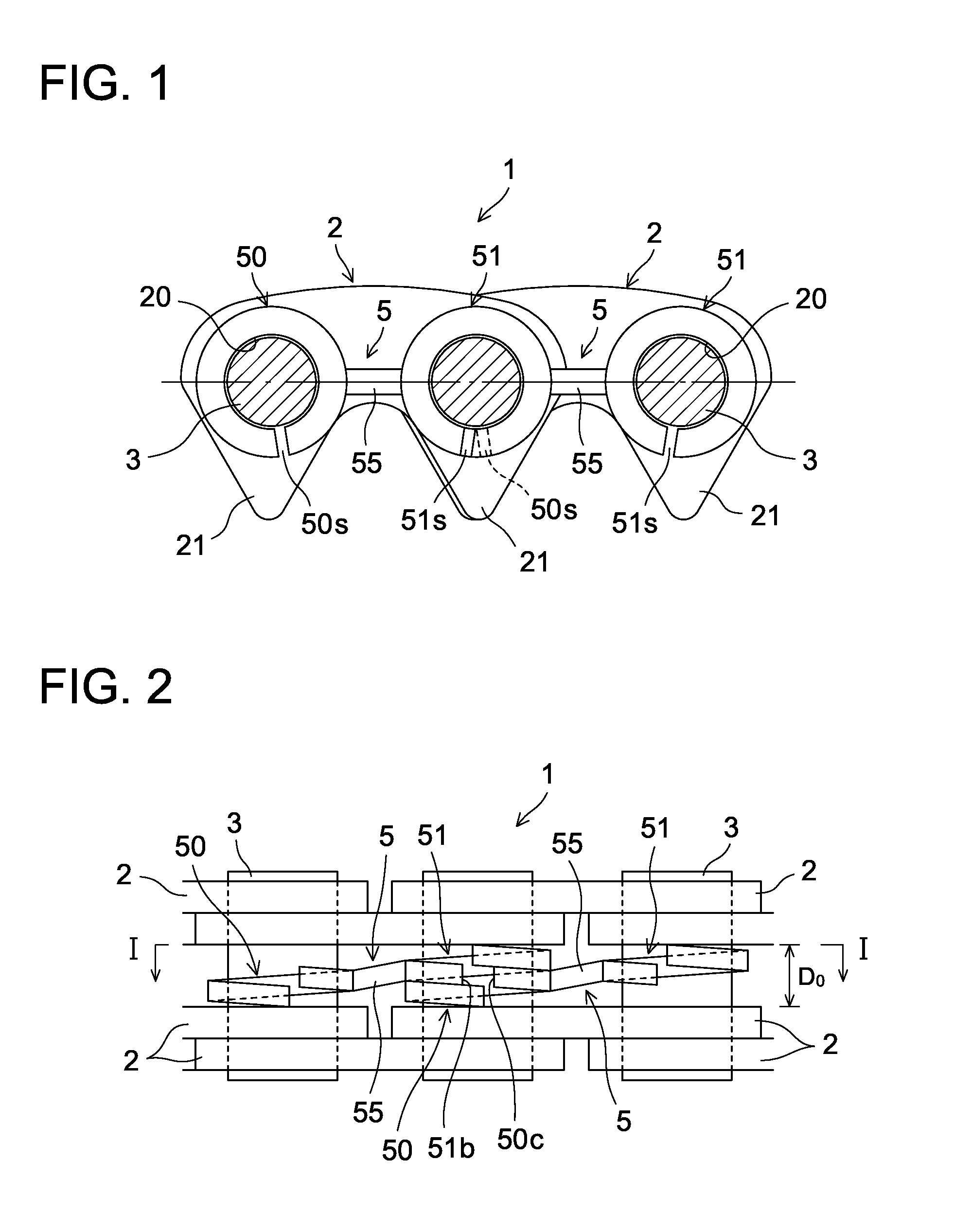
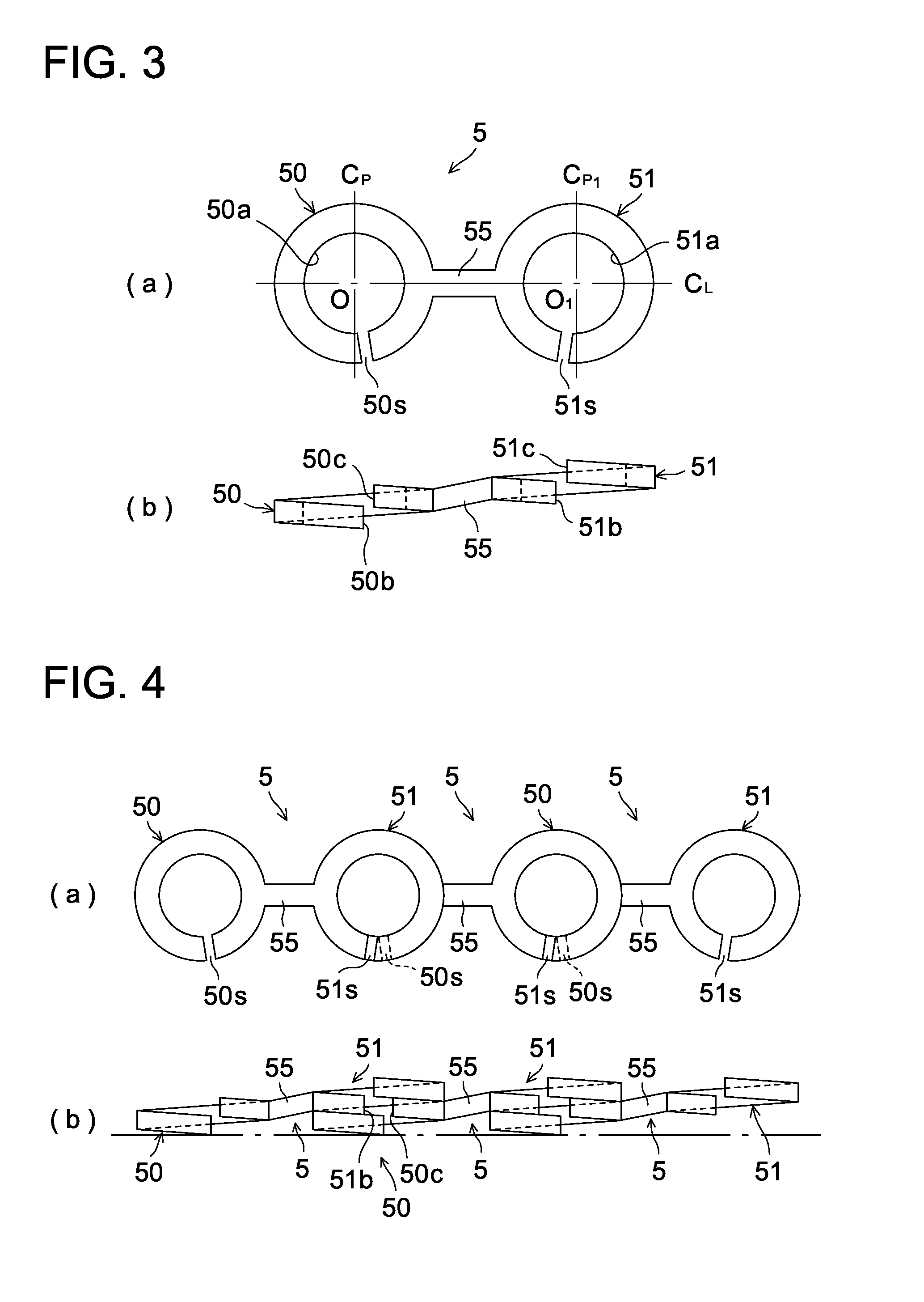
[0019]In the invention disclosed in claim 2, which is in accordance with the invention of claim 1, the spring washer parts are formed as coil shapes twisted by one turn, and a slit is formed between the starting edge and ending edge of said twisted coil shapes of the spring washer parts.
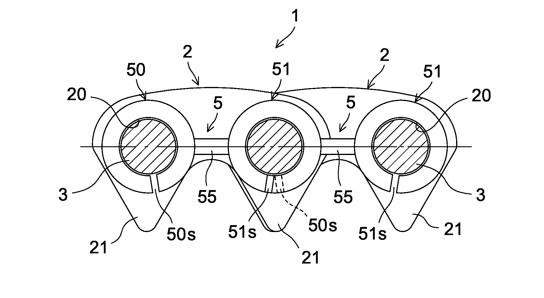
[0035]According to the present invention described above, the chain is provided with a backbend prevention mechanism in which a plurality of spring washer structures, consisting of a pair of left-right spring washer parts into which the linking pins are inserted, and linking parts for linking the areas between the spring washer parts, are disposed in the length direction of the chain, while adjacent spring washer structures in the chain length direction extend in the length direction of the chain in a state in which the spring washer parts of each are overlapping, and therefore when the chain links undergo backbend, the adjacent spring washer structures in the chain length direction flex as the links flex, and at this point the mutual rotation of the overlapping spring washer parts of the spring washer structures causes an increase in the thickness of the overlapping portions of the spring washer parts. This means that a
friction force acts between adjacent links in the chain width direction, increasing the bending resistance of the chain, and backbend of the links can be suppressed, so it is possible to suppress string vibration in the chain spans.
[0021]In the invention disclosed in claim 3, which is in accordance with the invention of claim 2, the starting edge of one of the overlapping spring washer parts is disposed opposite the ending edge of the other spring washer part.
[0022]In this case, it is possible to reduce the thickness of the overlapping portions of the spring washer parts, which makes it possible to
restrict increases in the chain width caused by assembling the spring washer structures therewith.
[0025]In the invention disclosed in claim 5, which is in accordance with claim 2, the slit in one of the overlapping spring washer parts is offset from the slit in the other spring washer part.
[0034]The chain according to the present invention may be any of the silent chain disclosed in claim 10, or the
roller chain or bush chain disclosed in claim 11.
[0035]According to the present invention described above, the chain is provided with a backbend prevention mechanism in which a plurality of spring washer structures, consisting of a pair of left-right spring washer parts into which the linking pins are inserted, and linking parts for linking the areas between the spring washer parts, are disposed in the length direction of the chain, while adjacent spring washer structures in the chain length direction extend in the length direction of the chain in a state in which the spring washer parts of each are overlapping, and therefore when the chain links undergo backbend, the adjacent spring washer structures in the chain length direction flex as the links flex, and at this point the mutual rotation of the overlapping spring washer parts of the spring washer structures causes an increase in the thickness of the overlapping portions of the spring washer parts. This means that a
friction force acts between adjacent links in the chain width direction, increasing the bending resistance of the chain, and backbend of the links can be suppressed, so it is possible to suppress string vibration in the chain spans.
[0036]Furthermore, in this case, when the links flex toward the meshing side with the
sprocket, if the overlapping spring washer parts mutually rotate in the opposite direction to when the links undergo backbend, the thickness of the overlapping portions of the spring washer parts does not increase because of the twisted structure of the spring washer parts, and therefore when the chain meshes, there is no increase in the bending resistance of the chain, which means that it is possible to prevent a reduction in the
power transmission efficiency of the chain during operation.
[0037]Moreover, in this case, even if the friction between the linking pins and pin holes causes elongation of the chain during operation, the linking pins are always inserted in the spring washer parts of the spring washer structures, and therefore the overlapping spring washer parts of adjacent spring washer structures in the chain length direction mutually rotate together with the links when said links undergo backbend, thereby causing an increase in the thickness of the overlapping portions of the spring washer parts. In this way, the backbend prevention mechanism is unaffected by chain friction, and is very durable.

