Planetary gear mechanism

a technology of planetary gear and gear mechanism, which is applied in the direction of gearing, differential gearing, mechanical equipment, etc., can solve the problems of high cost, large installation space, and inability to provide a large speed change ratio, and achieves small size, high torque, and large speed change ratio

Inactive Publication Date: 2012-04-26
JTEKT CORP
View PDF6 Cites 9 Cited by
  • Summary
  • Abstract
  • Description
  • Claims
  • Application Information

AI Technical Summary

Benefits of technology

[0028]In the planetary gear mechanism of the invention according to claim 1, as the third member as one of the input and output shafts rotates, the oscillating member eccentrically oscillates via the eccentric portion provided on the third member, and undergoes rotary motion about the eccentric axis. The oscillating member is formed with the first externally toothed gear that engages with (externally contacts and meshes with) the first internally toothed gear formed on the first member, and the rotational speed of the rotary motion about the axis of the input and output shafts (the central axis of the third member) is changed to the speed corresponding to the speed change ratio determined by the number of teeth of the first externally toothed gear and that of the first internally toothed gear.
[0029]The oscillating member is also formed with the second externally toothed gear that engages with (externally contacts and meshes with) the second internally toothed gear provided on the second member as the other of the input and output shafts. The oscillating member eccentrically oscillates and rotates at the speed to which the rotational speed has been changed by the first gear set (the first externally toothed gear and the first internally toothed gear), and the rotational speed of the eccentric oscillating rotation is changed to the speed corresponding to the speed change ratio determined by the number of teeth of the second externally toothed gear and that of the second internally toothed gear. Here, the second externally toothed gear is formed on the oscillating member, and the rotation whose speed has been changed by the second gear set (the second externally toothed gear and the second internally toothed gear) is delivered to the second member via the second internally toothed gear. Thus, in the planetary gear mechanism of the invention, the rotational speed at which the third member rotates is changed by both of the first gear set and the second gear set, and the resulting rotation is delivered from the second member. The oscillating member rotates in the direction opposite to that of the third member, and the second member rotates in the direction opposite to that of the oscillating member. Also, the planetary gear mechanism of the invention may change the speed of rotation of the second member and deliver it to the third member. In this case, the rotation is transmitted via the second member, the second internally toothed gear, the second externally toothed gear, the first internally toothed gear, the first externally toothed gear, the oscillating member, and the third member, in the order of description, so that the speed of the rotation is changed.
[0030]Thus, the planetary gear mechanism of the invention is constructed such that the rotational speed that has been changed by one of the first and second gear sets is further changed by the other gear set. With this arrangement, a large speed change ratio can be obtained by adjusting the speed ratios or gear ratios of the first gear set and the second gear set. In this connection, the speed ratio (reduction ratio) of each of the gear sets can be determined by adjusting the numbers of teeth of the externally toothed gear and internally toothed gear that constitute each of the gear sets.
[0031]Also, the planetary gear mechanism of the invention is constructed such that the two gear sets that change the speed are formed as a unit, to thus provide a speed reducer that is small in size but provides high torque and a large reduction ratio, which advantageously contributes to reduction in the size of the system. In particular, the first and second externally toothed gears are formed integrally on the oscillating member, so that the axial length of the oscillating member can be advantageously shortened, and the overall size of the planetary gear mechanism can be advantageously reduced.
[0032]In the planetary gear mechanism of the invention, high machining or working accuracy is required in formation of only the engaging faces of the first and second externally toothed gears provided on the oscillating member and the internally toothed gears engaging with the respective externally toothed gears (the meshing faces of the gears). In other words, high machining or working accuracy is not required in formation of the other portions. Thus, the planetary gear mechanism of the invention exerts a cost reduction effect.
[0033]In the known planetary gear mechanism, the inner pin holes through which the inner pins extend need to be formed in the externally toothed gear, and there is a limitation to reduction of the outside diameter of the externally toothed gear itself. On the other hand, the planetary gear mechanism of the invention, in which two externally toothed gears are provided on the oscillating face plate (that functions equally with the externally toothed gear), does not use any component that requires large space, like the inner pin holes. Consequently, the outside diameter can be advantageously reduced.

Problems solved by technology

On the other hand, the speed reducer of the cycloid type has a complicated mechanism for taking output out of eccentric oscillating rotation, and is likely to be available at a high cost.
However, the known cycloid differential planetary gear mechanism has a problem that it cannot provide a large speed change ratio (reduction ratio).
Therefore, in order to achieve an even larger reduction ratio (e.g., 100 or larger) with the speed reducer having the known mechanism, another stage of speed reduction mechanism or speed reduction unit must be added the upstream side of the input shaft or the downstream side of the output shaft, resulting in a significant increase in the cost and an increase in the installation space.
It is practically impossible or quite difficult to make this choice, eventually making it impossible to realize a structure that provides a large reduction ratio.

Method used


Image

  • Planetary gear mechanism
  • Planetary gear mechanism
  • Planetary gear mechanism

Examples


first embodiment

Another Modified Example of First Embodiment

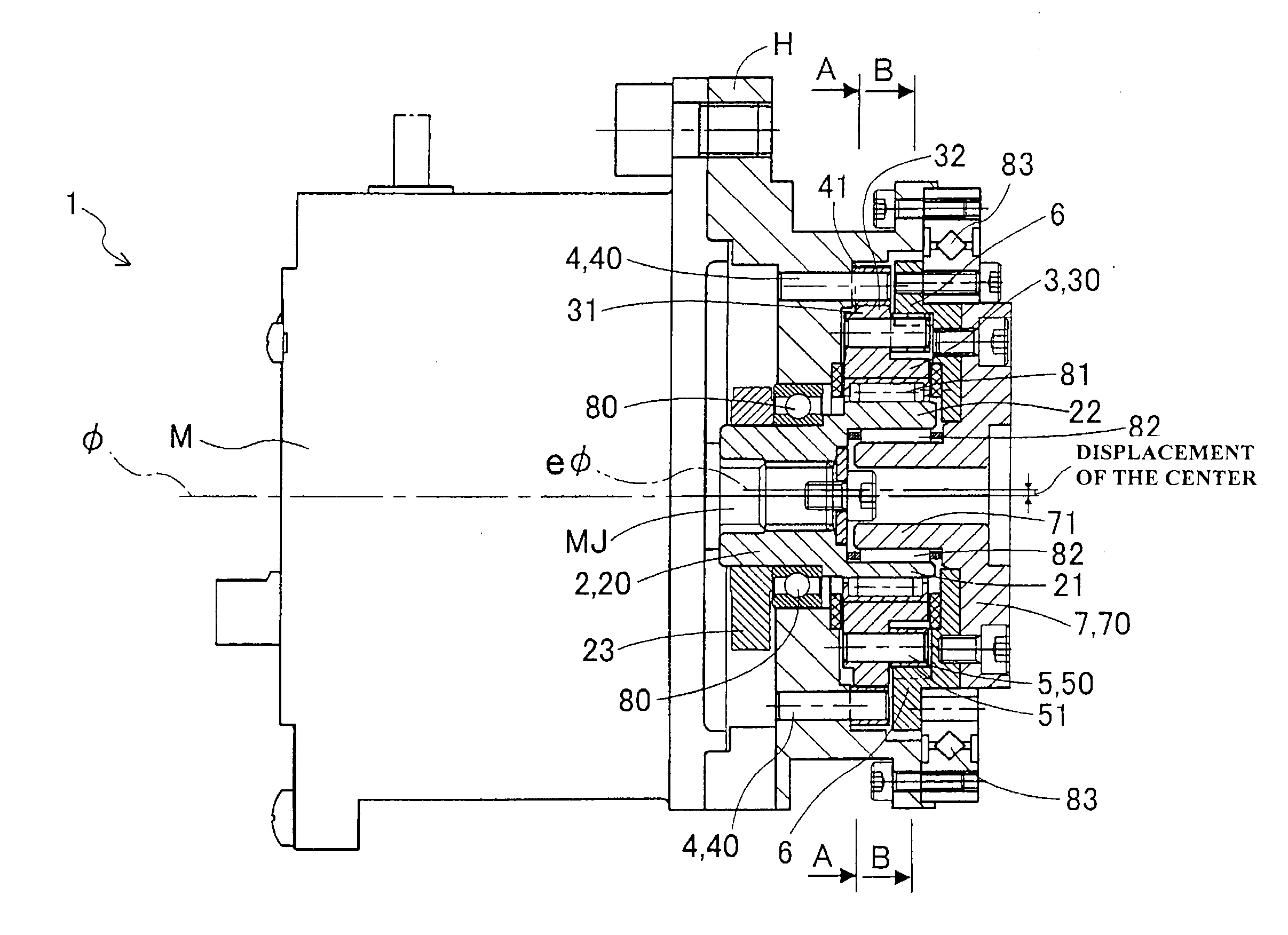
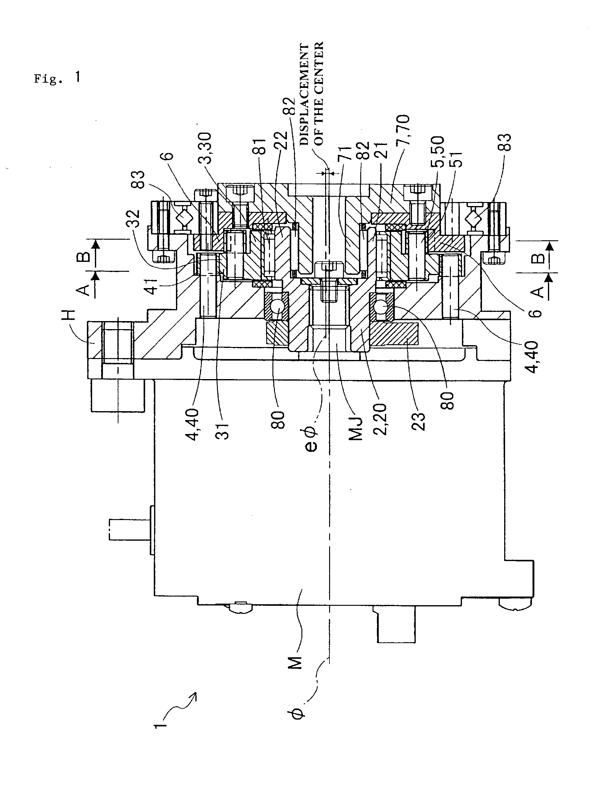
[0111]In the above-described embodiment, the gear mechanism of the invention is applied to the speed reducer 1 that transmits driving force of the motor M applied to the input shaft 2, to the output shaft 7, while reducing its speed. However, the gear mechanism may be applied to a speed increasing device that transmits driving force applied to the output shaft 7, to the input shaft 2, while increasing its speed.

Second Embodiment

[0112]Next, a speed reducer 1K according to a second embodiment will be described in terms of its differences from the speed reducer 1 as described above, with reference to FIG. 6 through FIG. 9. As shown in FIG. 6, a case C1 (corresponding to the first member of the invention) of a motor M1 (corresponding to the electric motor of the invention) is formed integrally with a housing of the speed reducer 1K. The case C1 also serves as the housing of the speed reducer 1K, and rotatably supports an output shaft 700 (corr...

second embodiment

Modified Examples of Second Embodiment

[0129]The inner ring of the output shaft supporting bearing 803 is not necessarily formed integrally with the output shaft 700, but an inner ring may be provided independently of the output shaft 700.

[0130]In the speed reducer 1K, the output shaft 700 may be nonrotatably fixed, and the case C1 may be rotatable about the axis of the input and output shafts. Also, the output shaft 700 and the case C1 may be both rotatable about the axis of the input and output shafts, and reduced-speed rotation may be delivered at a given ratio to the output shaft 700 and the case C1, respectively.

[0131]In the speed reducer 1 of the first embodiment, weight reducing holes serving as the counter balancer 23 may be provided in the input shaft 2.

[0132]In the speed reducer 1 of the first embodiment, the inner ring of the output shaft supporting bearing 83 may be formed integrally with the output shaft 7.

[0133]In the speed reducer 1 of the first embodiment, the input s...


PUM


Abstract

A planetary gear mechanism of the invention includes a housing, an input shaft that has an eccentric portion whose center lies on an eccentric axis, and is rotatable about the axis of input and output shafts relative to the housing, an oscillating face plate that eccentrically oscillates relative to the input shaft via the eccentric portion, and rotates about the eccentric axis, and an output shaft that is provided with a second internally toothed gear that internally contacts and meshes with a second externally toothed gear formed on the oscillating face plate, and is rotatable about the axis of the input and output shafts relative to the housing. The housing is formed with a first internally toothed gear that internally contacts and meshes with a first externally toothed gear formed on the oscillating face plate. As the input shaft rotates, a circumferential position at which each externally toothed gear meshes with the corresponding internally toothed gear changes, and rotation of the input shaft is transmitted at a reduced speed to the oscillating face plate, of which rotation is delivered at a further reduced speed to the output shaft.

Description

TECHNICAL FIELD[0001]The present invention relates to a planetary gear mechanism.BACKGROUND ART[0002]A speed reducer having a planetary gear mechanism is used for reducing the speed of rotation of a motor, for example. As one type of the planetary gear mechanism, there is widely known a planetary gear mechanism having a first shaft, an externally toothed gear mounted via an eccentric body provided on the first shaft such that the gear is eccentrically rotatable relative to the first shaft, an internally toothed gear which the externally toothed gear internally contacts and meshes with, and a second shaft coupled to the externally toothed gear via a means for transmitting only the rotational component of the externally toothed gear. As a specific example of this type of planetary gear mechanism, a cycloid differential planetary gear mechanism is known.[0003]The speed reducer using the cycloid differential planetary gear mechanism achieves a large speed reduction ratio with one reduct...

Claims


Application Information

Patent Timeline
Patent Type & Authority Applications(United States)
IPC IPC(8): F16H1/32
CPCF16H1/32
Inventor NAGUMO, KOUJIOTA, HIROMICHIHONDA, TOMOHIROSUZUKI, YOSHIHARUKATOH, YOSHINOBU
Owner JTEKT CORP
Why Eureka
Try Eureka