Ergonomic handpiece for laparoscopic and open surgery

a laparoscopic and open surgery technology, applied in the field of surgical tools, can solve the problems of physical constraints on the surgeon's ability to operate freely, and difficulty in accurate control

Inactive Publication Date: 2012-04-26
SRA DEV LTD
View PDF4 Cites 242 Cited by
  • Summary
  • Abstract
  • Description
  • Claims
  • Application Information

AI Technical Summary

Benefits of technology

[0006]It is hence an aspect of the present invention to provide a surgical tool and a mechanism for a surgical tool having enhanced ergonomic features which obviate the above problems and contribute to the above surgical requirements.

Problems solved by technology

These have been limited by inadequate mechanism designs, which impose physical constraints on the surgeons' ability to operate freely.
Accurate control is difficult, and even the most dextrous surgeons find that they can rotate the cutting plane in one direction but not rotate it back in the other direction.

Method used


Image

  • Ergonomic handpiece for laparoscopic and open surgery
  • Ergonomic handpiece for laparoscopic and open surgery
  • Ergonomic handpiece for laparoscopic and open surgery

Examples


fourth embodiment

[0093]Furthermore, any of the above structures may be mounted at different locations within a surgical instrument, in order to effect the required rotation, as will be described below and shown in FIG. 5. In this fourth embodiment, a distal portion of the drive assembly of the handpiece of the tool comprises fixed stator windings 40, mounted to a manually-graspable handle 5 of the tool, while magnetic rotor elements 41 are attached to a distally-extending handpiece member 2 (which may comprise the waveguide 3 or an equivalent energy transmission member) and a proximally-extending transducer 12 through a connecting mechanism 45. The member 2, the magnetic rotor elements 41, the connecting mechanism 45 and the transducer 12 may thus be rotated about a longitudinal axis in the sense of arrow 42, relative to the handle 5 and a remainder of the casing 1 of the handpiece.

[0094]Alternatively, electromagnetic elements 50 may be incorporated into the casing 12a, 12b of the transducer 12, and...

second embodiment

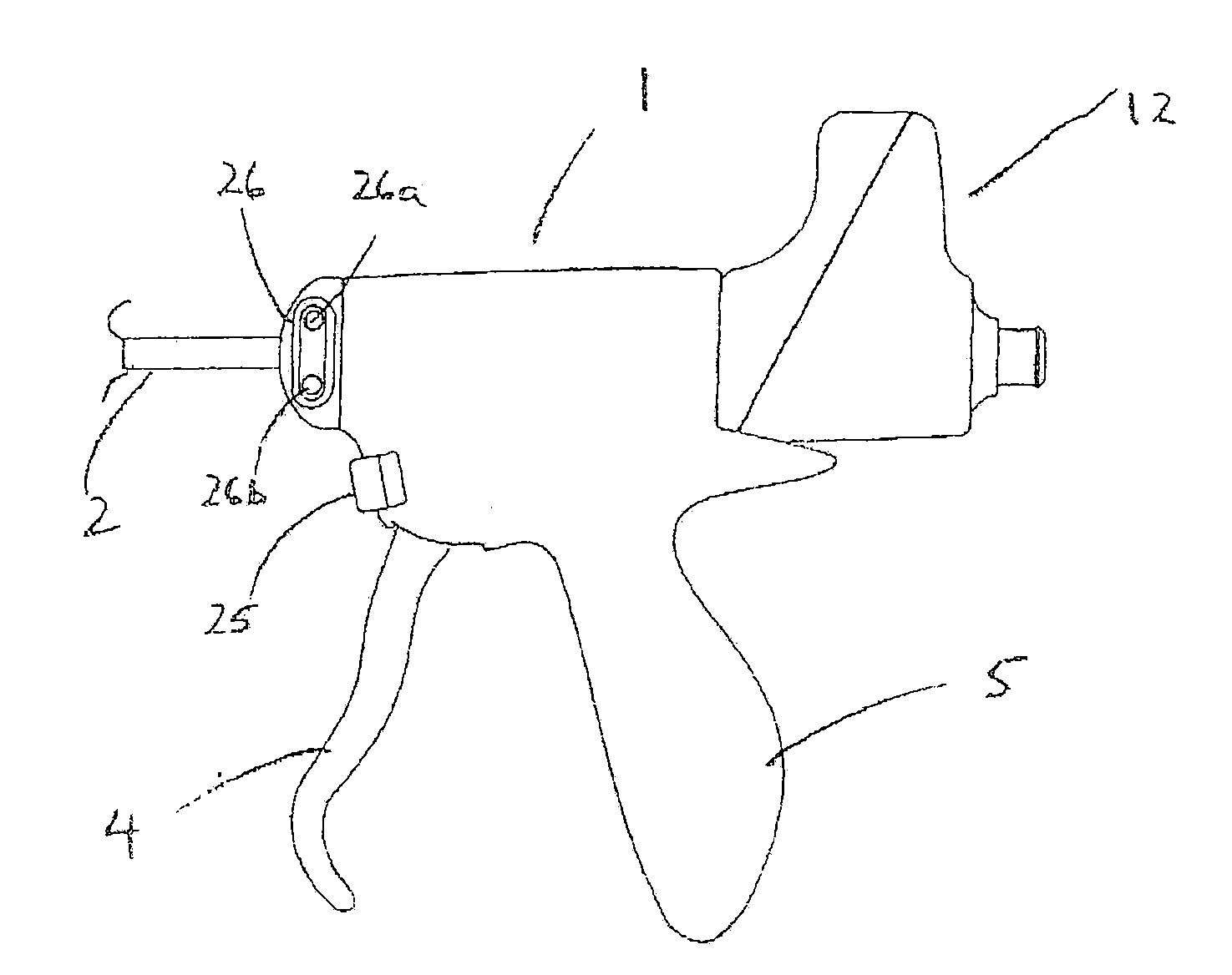
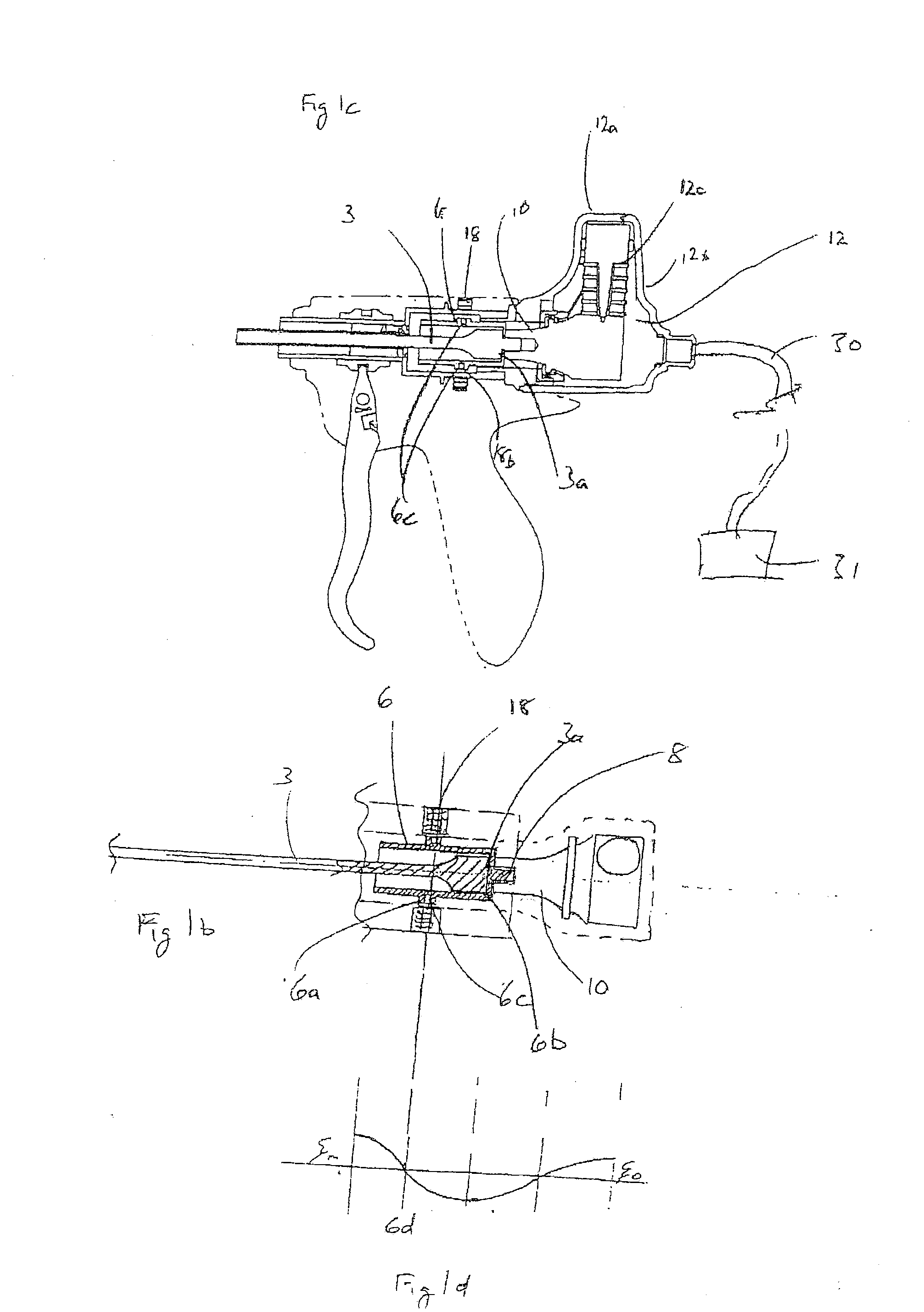
[0096]An alternative means of rotation of the cutting plane of the tool may be effected by the second embodiment illustrated in FIGS. 3a and 3b. The aforementioned isolating sleeve 6, with its same nodal plane 6d, is provided with a raised circumferential flange having a profile comprising a gear ring 6g. A tangentially-mounted electric motor 11, fixed to handpiece casing 1 has a gearbox 11b operatively connected thereto, provided with an output worm gear 11a, which is operatively engaged with said gear ring 6g. The motor 11 is activated by switches 26a and 26b on the exterior of the handpiece casing 1 and conveniently positioned for digital access.

[0097]In the tools illustrated, which contain ‘L-shaped’ transducers 12 adapted to produce torsional mode ultrasonic vibrations, rotation of the cutting plane would be limited to ±90° about a neutral plane. If an alternative axisymmetric transducer 12 were used, both the above approach and that described in the context of FIGS. 1a to 1c w...

third embodiment

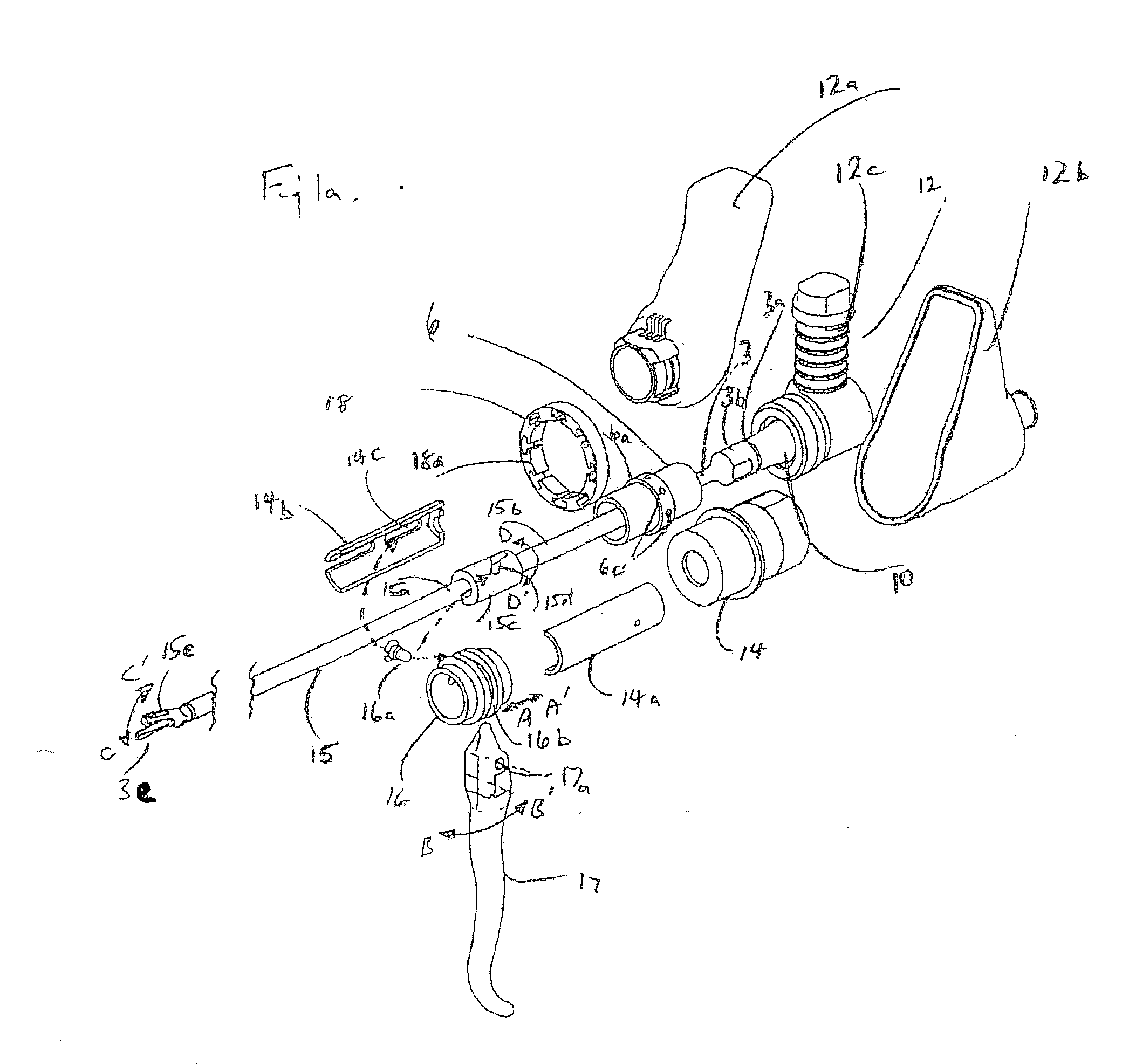
[0098]an arrangement for rotating the cutting plane is shown in FIGS. 4a and 4b. The acoustic isolating sleeve 6 is provided with a helically-extending slot 6h, within which is held a hardened ball 6k (see FIG. 4a). The ball 6k is compelled to move in a direction parallel to the longitudinal axis of the waveguide 3 by slideable knob 9b, which is constrained to travel within a longitudinal slot 9a in an outer sleeve 9. Slideable knob 9b is provided with a protruding socket 9c, which receives part of the ball 6k and which also passes through a longitudinal slot 7c in an inner slide sleeve 7. Longitudinal movement of the knob 9b, in the direction of arrows E and E1, thus causes a corresponding rotational displacement of said acoustic isolator 6, and hence the transducer 12 and waveguide 3 connected thereto, as indicated by arrows D and D1. The inner slide sleeve 7 is operatively connected at its distal end to tube holder 14, and at its proximal end to the transducer casing 12a, in orde...


PUM


Abstract

A surgical tool having an elongate shaft, with a directional operative element at its distal end, is provided with a mechanism to rotate the shaft and the operative element about a longitudinal axis shaft. This allows the operative element to be aligned with an element of tissue without excessive hand movement by the user. In a preferred version, the mechanism is electrically powered and is regulated to produce smooth, controlled, accurate motion between selected rotational positions. The mechanism may include a linear magnetic motor drive to move a drive element longitudinally along the tool. This drive element is engaged with a helical formation on a drive shaft, such that longitudinal motion of the drive element is converted to rotational motion of the drive shaft, and of the shaft and operative element, to which the shaft is mounted.

Description

CROSS REFERENCE TO RELATED APPLICATIONS[0001]This application claims priority of United Kingdom applications GB1017968.7 filed on Oct. 23, 2010, GB1019794.5 filed on Nov. 22, 2010, GB1020672.0 filed on Dec. 6, 2010, and GB1102034.4 filed on Feb. 4, 2011, the entire contents of all of these applications being hereby incorporated by reference herein.BACKGROUND ART[0002]The present invention relates to a surgical tool, and to a mechanism for its operation. More particularly, but not exclusively, it relates to such a tool having improved ease of manual control.[0003]Over the past 20 years, much effort has been applied to the development of specialised surgical instruments which allow complex procedures to be performed with predictable outcome. (For example, see U.S. Pat. No. 6,887,252; U.S. Pat. No. 6,056,735; U.S. Pat. No. 6,063,050 and U.S. Pat. No. 6,468,286). Many of these devices are designed to manipulate and dissect biological tissues. These devices may be manually operated or al...

Claims


Application Information

Patent Timeline
Patent Type & Authority Applications(United States)
IPC IPC(8): A61B18/18
CPCA61B17/29A61B17/320092A61B2017/00017A61B2019/4857A61B2017/2929A61B2017/320096A61B2017/00398A61B2090/0811A61B2017/320098A61B2017/320094A61B2017/320093A61B90/08A61B17/00234A61B18/04
Inventor YOUNG, MICHAEL JOHN RADLEYLEAVER, CHRISTOPHER JOHNWRIGHT, NICHOLAS CHARLESMANLEY, PETER JAMES
Owner SRA DEV LTD
Why Eureka
Try Eureka