Handheld sprayer with removable cartridge and method of using same

a sprayer and cartridge technology, applied in the field of devices, can solve the problems of inability to carry out the operation of the sprayer through the user, etc., to achieve the effect of convenient grounding of the spray device through the user, improving balance, and enhancing the ergonomic features of the spray devi

Inactive Publication Date: 2010-03-09
EFIELD INNOVATIONS
View PDF35 Cites 5 Cited by
  • Summary
  • Abstract
  • Description
  • Claims
  • Application Information

AI Technical Summary

Benefits of technology

[0011]Optionally, the cartridge contains a liquid between the piston and the distal end of the fluid chamber. In another option, the cartridge body is tubular in shape. In the present context, the term “tubular” refers to a hollow shape which has in cross-section a geometrical or irregular form. The tubular body may be either axially elongate or axially squat, where the former refers to the extension of such form substantially along an axis a distance sufficient to define a fluid chamber, and the latter refers to an axial dimension of the fluid chamber that is relatively small when compared to the radial dimension. Additionally, the cartridge includes numerous nozzles that are fluidly coupled to it so that upon the application of force by the moving piston to the fluid, the fluid passes through the nozzles (which may be interconnected along a header or related manifold). For EHD spraying, the pressure necessary to move the fluid is nominal, as needed at a minimum to continuously provide fluid to replace that which is dispensed at what are referred to as Taylor cones formed at the nozzles. The nozzles are preferably fixed to the cartridge such that they may be disposed of or reusable together. This also promotes ease of use. Alternatively, the nozzles may be separable and reusable from the cartridge. The nozzles, manifold or both can be made of a conductive plastic material, using as base materials polymers, for example polycarbonate, high density polypropylene, or preferably polypropylene, acrylonitrile-butadiene-styrene (ABS) and high density polyethylene (HDPE), which can be appropriately compounded as known in the art to exhibit conductive properties. Preferably, such materials exhibit surface resistivity from approximately 102 to 1014 ohm / square, and volume resistivity of 102 to 1014 ohm / cm. Alternatively, the nozzles may be made of other electrically conductive (for example, metallic) materials that can be cast or otherwise formed into the appropriate geometry. The nozzles are preferably electrically connected to a high voltage source within the sprayer. In either way, the EHD sprayer can impart the necessary charge to the droplets of liquid that are discharged from the nozzles. As stated above, there are various ways to establish fluid connection between the fluid chamber and the nozzles in such a way as to reduce the likelihood of leakage. In one form, the cartridge includes a septum disposed at the distal end. A cap may also be disposed at the distal end; the cap cooperative with the septum such that upon engagement of the two, the cap forms the aperture in the distal end and forms the sealing force. In another form, a stop-cock is disposed at the distal end to allow for repeated opening and closing of the cartridge. In either form, such act as a closure device configured to keep a liquid disposed within the cartridge from exiting through the distal end.
[0014]Optionally, the handle comprises a grip for engaging a user's hand. In the present context, the grip is the portion of the handle that comes into contact with the user's hand. At least a portion of the grip (such as the trigger or related control member) can be made from a material such as a metal, an electrically conductive plastic, electrically conductive polymer, electrically conductive rubber or combination thereof. This facilitates grounding of the spray device through the user. The trigger can be used to commence and halt operation of the spray device. In another option, a longitudinal dimension of the handle and a longitudinal dimension of the cartridge are substantially aligned along a common longitudinal axis, while in another, they are angularly disposed relative to one another in an offset manner, thereby enhancing ergonomic features of the spray device. In the offset configuration, the angle formed between the longitudinal dimensions is up to thirty degrees. In either configuration, the center of gravity of the cartridge and the handle is located along a segment of the grip during at least a portion of operation of the spray device, thereby improving balance. The cartridge may be rotatably positionable about its longitudinal axis such that a preferred spraying pattern made be employed while keeping the user's hand position relatively constant. The cartridge can be rotated in angles of up to plus or minus ninety degrees from a neutral position (i.e., the position assumed by the cartridge upon normal connection with the handle of the spray device). The spray device may further include a frame substantially similar to that described previously. An interface defined between the cartridge and the handle may include a load-bearing mounting surface on the handle that cooperates with a complementary surface on the frame such that at least a portion of the force acting on the piston and screw during operation is not transmitted to the drive mechanism, but is carried by the load-bearing mounting surface. This can result in smaller, simpler components being used in the cartridge. Optional complementary surfaces disposed on the driver and the lead screw allow self-adjusting connection between them.
[0015]The cartridge can be equipped with one of various forms of discharge closure means, examples of which include a septum or a stop-cock valve (the latter formed in an end cap) and operable to either establish fluid flow or seal the cartridge as previously discussed, either of which are placed at the distal end of the fluid chamber to prevent leakage or spillage of the liquid when the device is not in use. This is especially valuable in situations where highly concentrated fluids are placed in the cartridge. The spray manifold is electrically conductive, and is in fluid communication with the discharge aperture. In addition, the nozzles can be made electrically conductive, and in fluid communication with the spray manifold. In another form, the nozzle tips themselves do not have to be electrically conductive. The nozzle could be nonconductive with a conductive coating on the outside or inside to help establish the proper electric fields. Where the formulation of the fluid is sufficiently conductive, it would be enough that the high voltage contact the fluid somewhere upstream of the nozzles. Optionally, the handle includes a grip made from a metal, an electrically conductive material including electrically conductive plastic, electrically conductive polymer, electrically conductive rubber, and combinations thereof. In another option, the remainder of the handle could be made from the same materials as the grip.

Problems solved by technology

Unfortunately, the above-mentioned cartridge is prone to leakage, especially in regions between the outer periphery of the piston and the inner wall of the cartridge, as well as the threaded space between the screw and the piston.
In an application where a cartridge of this type may be used in a device with electronics, the fluid can potentially leak into regions where electronic and other liquid-intolerant componentry resides.
As well, when the cartridge or device is being stored during long periods of time during shipping, storage, display or between uses, an unacceptable quantity of fluid may be lost.
This problem is particularly acute in situations where the liquid is expensive or hazardous, such as a pesticide, herbicide, flammable materials or the like.

Method used


Image

  • Handheld sprayer with removable cartridge and method of using same
  • Handheld sprayer with removable cartridge and method of using same
  • Handheld sprayer with removable cartridge and method of using same

Examples


Embodiment Construction

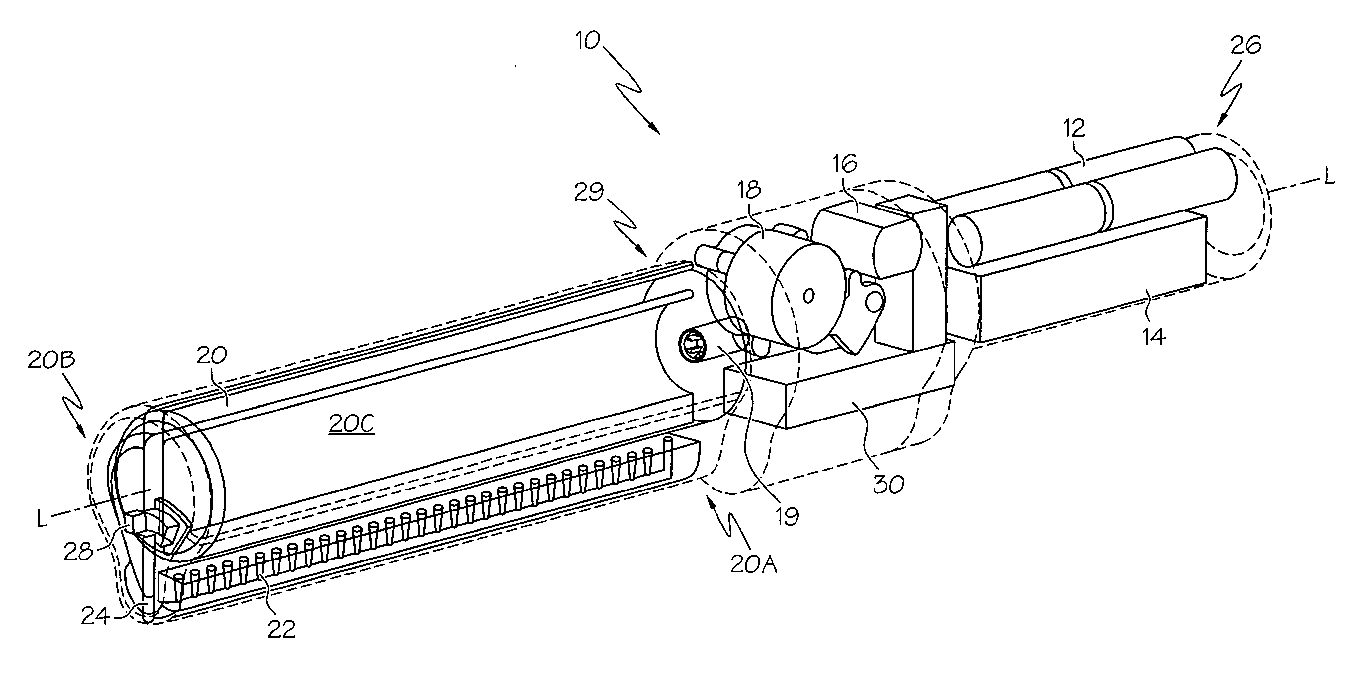
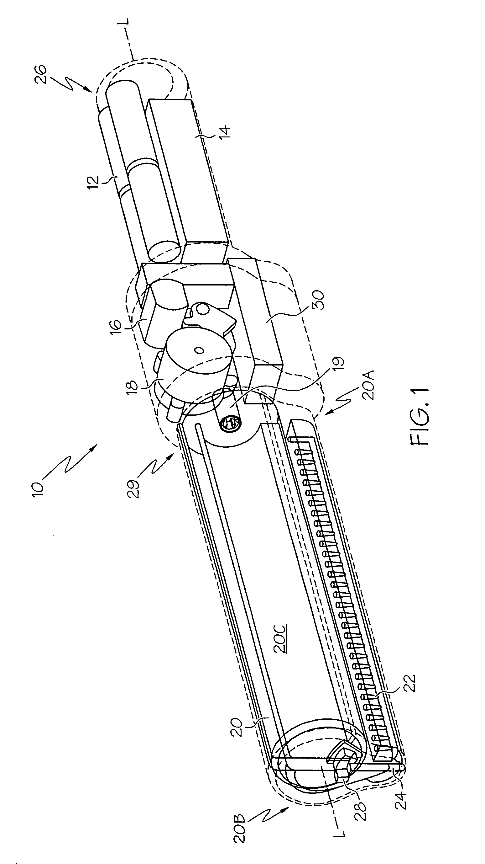
[0041]Referring first to FIGS. 1 and 13, a sprayer 10 includes a handle 26, a cartridge interface 29 and fluid-containing cartridge 20. An array of nozzles 22 are situated beneath cartridge 20, and are in fluid communication therewith to dispense a fluid. The handle 26 is used to house a power supply 12, a converter (also referred to as an electronics or circuit board) 14, a motor 16, a drive mechanism 18 and driver 19, and a high voltage multiplier 30 (also referred to as a voltage multiplier circuit). In the present context, the term “high voltage” and its variants is used to represent increases in voltage over that provided by the power supply 12 due to the operation of the voltage multiplier 30, rather than as indicia of a particular voltage level. By way of example, for a voltage measured at the output of the power supply 12 of six volts, a voltage of thousands of volts measured at the output of the voltage multiplier 30 would constitute a high voltage. The power supply 12 may ...


PUM


Abstract

A cartridge for a handheld electrohydrodynamic (EHD) spraying device and a spraying device incorporating the cartridge. The cartridge is disposable, and can contain therapeutic products. The device includes a wetted lead screw with a compliant seal, where the placement of the seal relative to the screw inhibits leakage during both cartridge use and storage. A frame disposed within the cartridge acts as a load-transferring mechanism for the weight of the cartridge to a handle of the spraying device.

Description

[0001]This application claims the benefit of the filing date of U.S. Design Patent Application entitled HANDLE, (application Ser. No. 29 / 261,411), and U.S. Design Patent Application entitled HANDLE, (Application Ser. No. 29 / 261,452), both filed Jun. 13, 2006.BACKGROUND OF THE INVENTION[0002]The present invention relates generally to devices for spraying finely dispersed liquids, and more particularly to the use of a disposable cartridge that is compatible with a handheld electrohydrodynamic (EHD) spray device.[0003]Spraying using EHD technology (also referred to as electric field effect technology (EFET)) is a process where fluids or other bulk solutions are dispensed through electrically-charged nozzles. In an EHD spray nozzle, the material to be sprayed flows through a region of high electric field strength made possible by the application of a high voltage to the nozzles and associated nozzle geometry. The high voltage causes the fluid material to acquire an electric charge; the ...

Claims


Application Information

Patent Timeline
Patent Type & Authority Patents(United States)
IPC IPC(8): B05B5/00
CPCB05B5/1691B05B9/0838
Inventor LIND, JAMES J.TREES, GREGORYZAMBANINI, JOSEPH E.GRAHAM, BRIANHARPHAM, R. READE
Owner EFIELD INNOVATIONS
Why Eureka
Try Eureka