Bone Screw For Orthopedic Apparatus

a technology for orthopedic devices and screws, applied in the field of screws, can solve the problems of limited bone attachment of orthopedic reinforcements, and achieve the effects of uniform loading, uniform loading, and uniform lengthwise tension loading

Inactive Publication Date: 2012-04-26
PITBLADDO RICHARD B
View PDF2 Cites 12 Cited by
  • Summary
  • Abstract
  • Description
  • Claims
  • Application Information

AI Technical Summary

Benefits of technology

[0008]The present invention provides bone screw designs whereby the screw deforms on the same order as the bone, thus providing substantially uniform loading along a substantial portion of the length of a thread of the bone screw. The lengthwise tension loading is much more uniform than the tension loading in the prior art. In fact, some of the embodiments of the present invention provide substantially uniform loading along the entire length of the thread.
[0009]A bone screw of the present invention evenly distributes stress by matching the effective cross-sectional area of the bone screw times its modulus of elasticity with the effective cross-sectional area of the parent material (i.e. bone) times its modulus of elasticity so that they are preferably substantially equal to each other.

Problems solved by technology

The attachments of orthopedic reinforcements to bone are limited by how well the screws inserted into the bone secure the reinforcements.
This is a major drawback of present practice in the applications where attachment strength is important.

Method used


Image

  • Bone Screw For Orthopedic Apparatus
  • Bone Screw For Orthopedic Apparatus
  • Bone Screw For Orthopedic Apparatus

Examples


Embodiment Construction

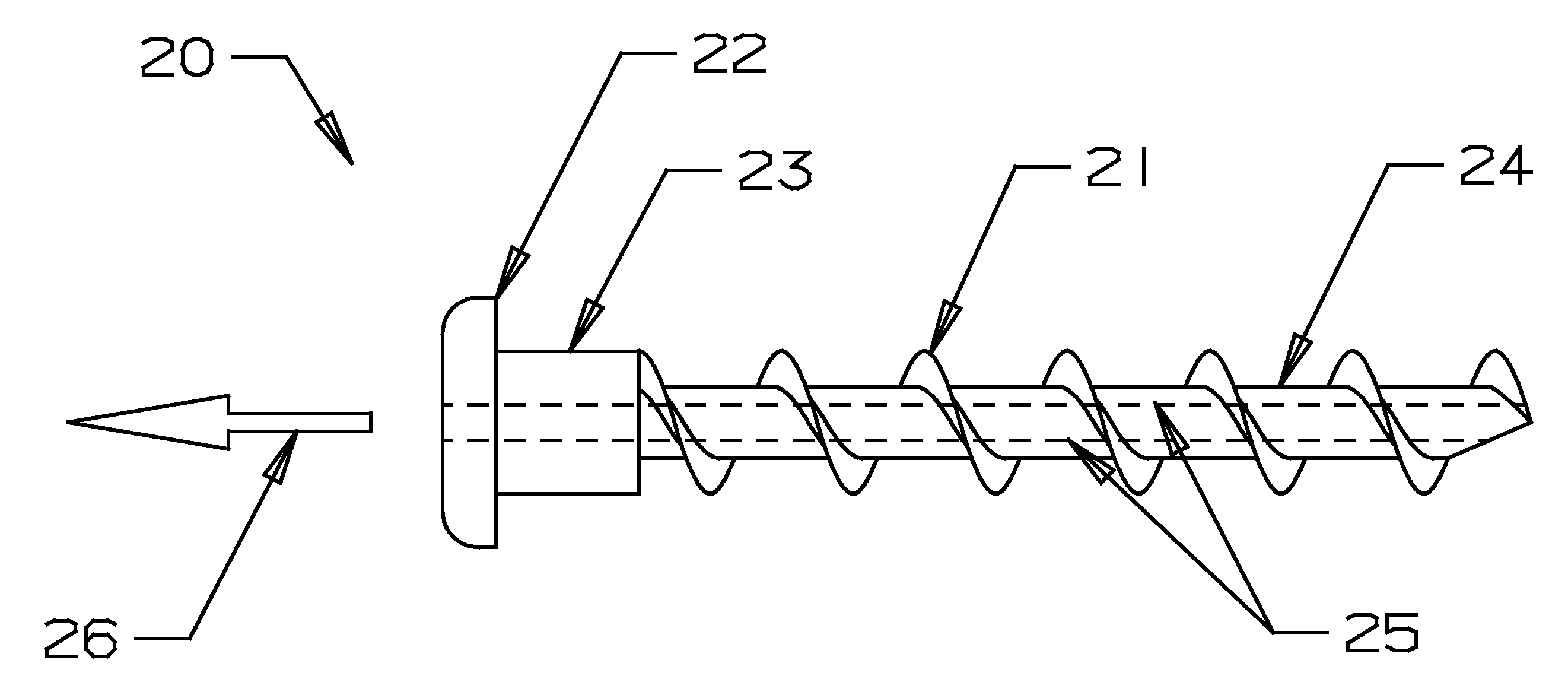
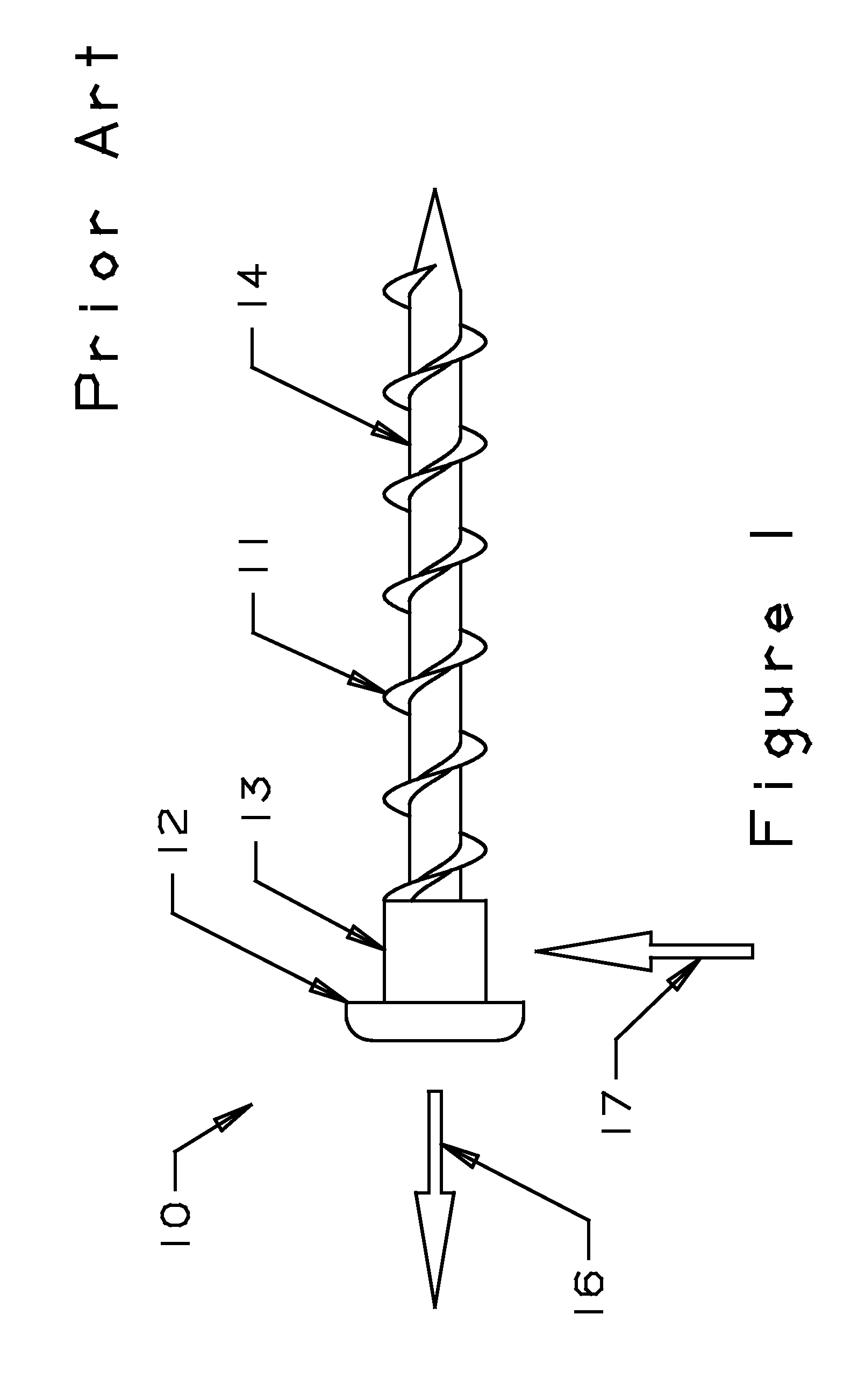
[0031]A standard screw made of stainless steel or titanium is much more rigid than the bone into which it is inserted. When a lengthwise / longitudinal tension load is applied to the screw, the bone deforms much more readily than the screw. The loading of the bone screw is not at all uniform along a length of the thread. Thus, only a few sections of the thread of the screw support the entire load. If the load on the bone is too high at these sections, the bone yields to failure at these sections and transfers the stress to other sections of the thread. Thus, there is a cascading phenomenon until the bone at all sections of the thread fails and the attachment is broken.

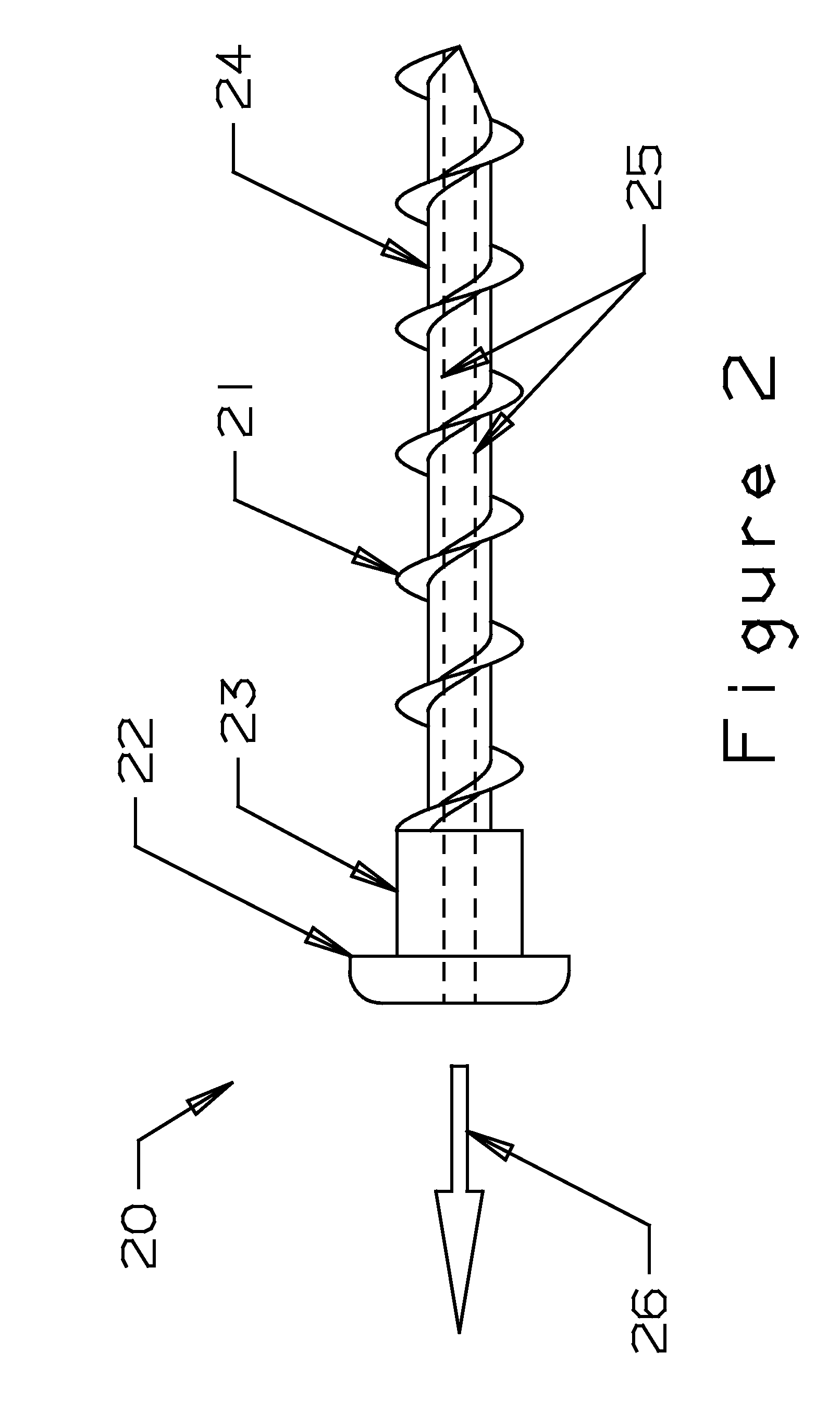
[0032]The present invention includes bone screws with different configurations in various embodiments. There are two different groups of embodiments. In one group of embodiments, the shape of the bone screw is varied to decrease the total cross-sectional area of the bone screw. In another group of embodiments, the materi...


PUM


Abstract

A bone screw deforms on the same order as the bone, thus providing substantially uniform loading along an entire length of the thread of the bone screw. The bone screw evenly distributes stress by matching the effective cross-sectional area of the bone screw times its modulus of elasticity with the effective cross-sectional area of the parent material (i.e. bone) times its modulus of elasticity so that so that the linear deformation of each is preferably substantially equal to the other.

Description

REFERENCE TO RELATED APPLICATIONS[0001]This application claims one or more inventions which were disclosed in Provisional Application No. 61 / 508,191, filed Jul. 15, 2011, entitled “BONE SCREW FOR ORTHOPEDIC APPARATUS”.[0002]This is also a continuation-in-part application of copending application Ser. No. 12 / 170,950, filed Jul. 10, 2008, entitled “BONE SCREW FOR ORTHOPEDIC APPARATUS”, which claimed priority from Provisional Application No. 60 / 949,596, filed Jul. 13, 2007, entitled “BONE SCREW FOR ORTHOPEDIC APPARATUS”.[0003]The benefit under 35 USC §119(e) of the United States provisional applications is hereby claimed, and the aforementioned applications are hereby incorporated herein by reference.BACKGROUND OF THE INVENTION[0004]1. Field of the Invention[0005]The invention pertains generally to the design of screws to secure orthopedic reinforcements to bones.[0006]2. Description of Related Art[0007]The attachments of orthopedic reinforcements to bone are limited by how well the sc...

Claims


Application Information

Patent Timeline
Patent Type & Authority Applications(United States)
IPC IPC(8): A61B17/86
CPCA61B17/864A61B17/866A61C8/0096A61B17/869A61B2017/0649A61B17/8685
Inventor PITBLADDO, RICHARD B.
Owner PITBLADDO RICHARD B
Why Eureka
Try Eureka