Person Moving Devices For Moving Persons Of Limited Mobility

a technology for moving devices and people, applied in the direction of nursing beds, transportation and packaging, wheelchair/patient conveyancing, etc., can solve the problems of caregivers' back injuries and run a significant risk

Active Publication Date: 2012-05-03
HAPAI TRANSFER SYST LTD
View PDF30 Cites 19 Cited by
  • Summary
  • Abstract
  • Description
  • Claims
  • Application Information

AI Technical Summary

Benefits of technology

[0058]Preferably, the device further comprising one or more ground wheels which engage the floor at least when the device is in its transport position to enable the device carrying a patient to be moved to transport the patient.
[0059]In all aspects, the movement of the patient from the load-unload position to the transport position and from the transport position to the load-unlo

Problems solved by technology

Moving one person by another requires significant strength of the caregiver (mover), and can run a sig

Method used


Image

  • Person Moving Devices For Moving Persons Of Limited Mobility
  • Person Moving Devices For Moving Persons Of Limited Mobility
  • Person Moving Devices For Moving Persons Of Limited Mobility

Examples


first embodiment

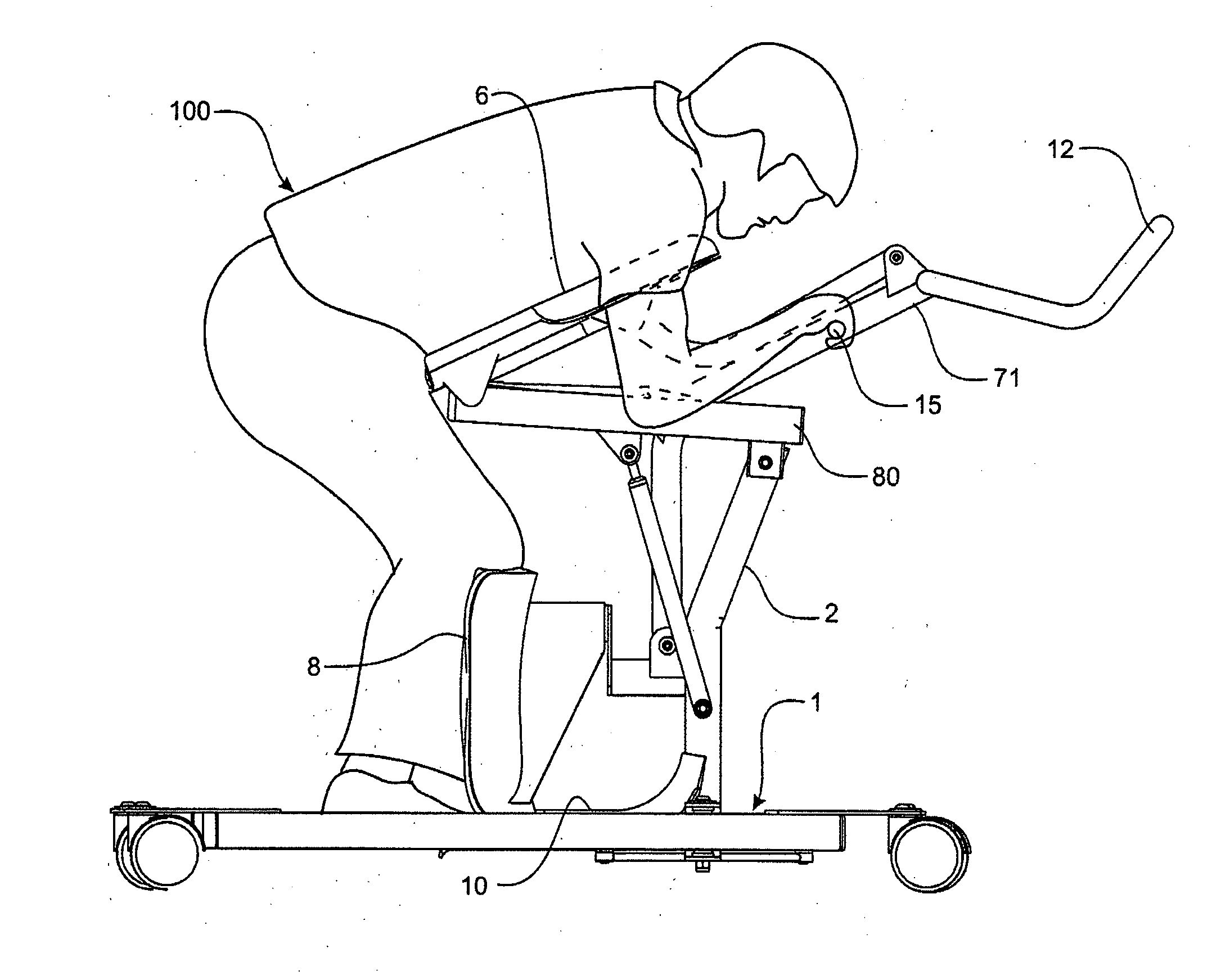
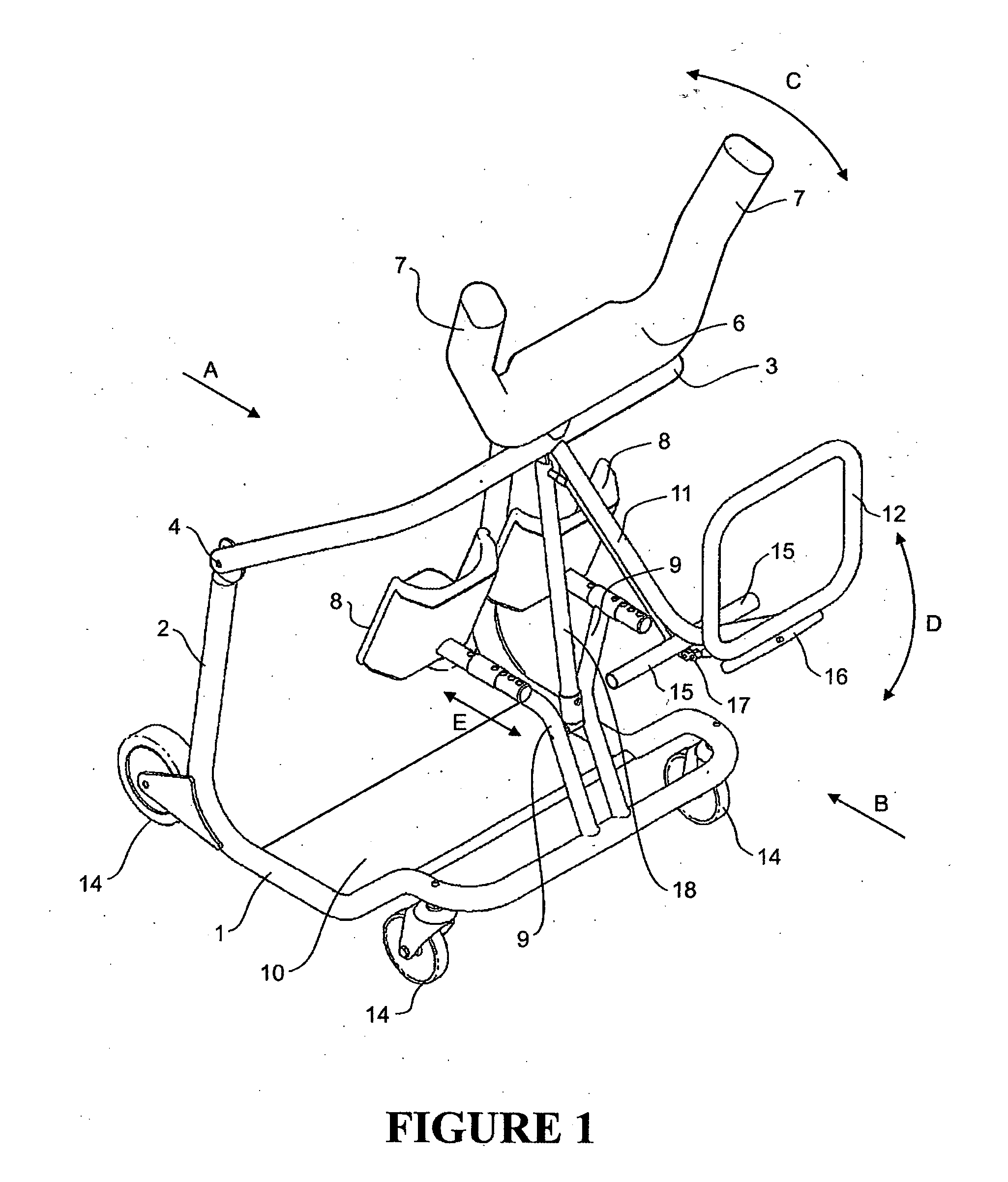
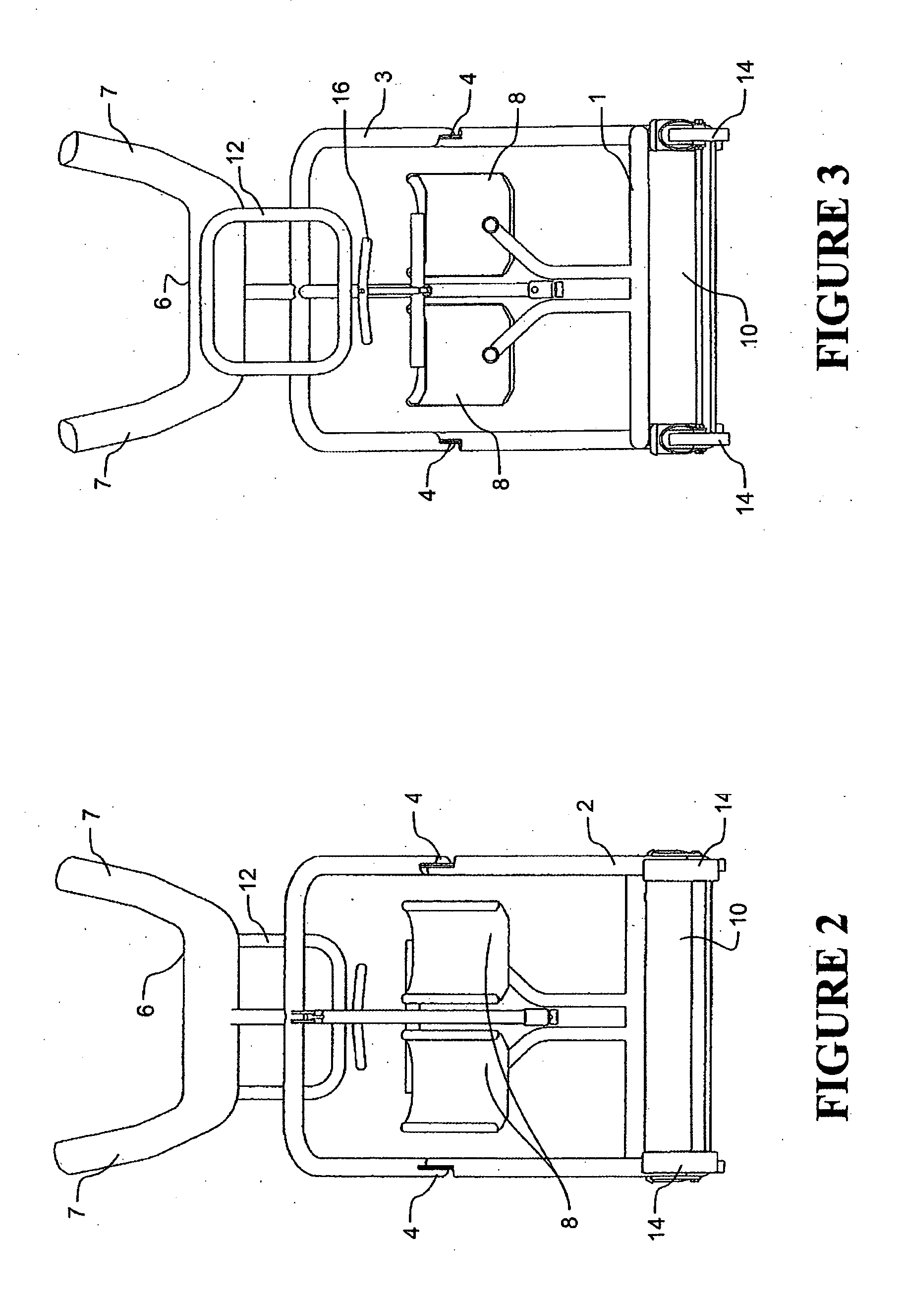
[0080]The first embodiment patient mover of the invention shown in FIGS. 1 to 9 is formed largely of bent metal tube or pipe, but in other embodiments may be otherwise constructed.

[0081]The lower floor engaging frame part has an approximate square u-shape as shown and comprises upright elements 2. The upper frame part is indicated at 3 and is pivotally mounted to the top of the uprights 2 of the lower frame part 1 at spaced pivot points 4, for movement of the upper frame part 3 relative to the lower frame part 1 as indicated by arrow C in some figures, between a load-unload position and transport position, as shown in FIG. 9.

[0082]The upper frame part includes a cradle 6 facing a patient side of the device, which is preferably covered with a resiliently compressible material such as a high density foam material or is otherwise padded, and which is positioned to engage the patient's chest when the patient is carried by the patient mover. In the embodiment shown the cradle 6 includes ...

second embodiment

[0090]FIGS. 11 to 19 illustrate a second embodiment of patient mover of the invention, which again is formed largely of bent metal tube or pipe but may be otherwise constructed. Unless indicated otherwise, similar reference numerals as in FIGS. 1 to 9 indicate similar elements such as cradle 6 / 7 and handle 11 / 12 for example.

[0091]In this embodiment a lower floor engaging frame part 1 again has an approximate square u-shape as shown and mounts a central upright 3. Referring particularly to those figures which show the patient mover of this embodiment in side elevation, a section 1a of the lower frame part on either side is formed with a low radius of curvature in a vertical plane (or no radius of curvature so that section 1a is flat or substantially flat) and sections 2 on the patient side of the device are formed with a decreased radius of curvature or at least are cranked away from the sections 1a as shown. Rollers 14a (or skids) are provided which protrude slightly below the frame...

third embodiment

[0096]FIGS. 20-27 illustrate a third embodiment of patient mover of the invention which is similar to that of FIGS. 1-9. Unless indicated otherwise again similar reference numerals as in FIGS. 1-9 indicate similar elements. In this embodiment the lower floor engaging frame part 1 comprises a single upright element 2 on one side, and the upper frame part comprises a single part 3 on the same side and pivotally mounted by (single) pivot 4 to the top of the single upright element 2.

[0097]The upper and lower frame parts are formed of relatively large diameter tube for strength. The upper frame part includes transverse part 3a to which the cradle 6 is mounted. Telescopic stabilising strut 18 which may also provide limit stops for movement between the load-unload and transport positions is provided on the one side only of the device. As before the device may also include a latch mechanism which is engaged when the upper frame part 3 is returned to the transport position, to lock the upper...


PUM


Abstract

A person moving device for moving a person of limited mobility. The device comprises a lower floor engaging frame part (1) and an upper patient carrying part (6) adapted to carry a patient by engaging the patient's torso from the front and which is mounted to the lower frame part for movement between a patient load-unload position and a patient transport position. The upper patient carrying part being mounted to the lower frame part for curvilinear movement about an axis extending across the patient and positioned so that the patient.s torso moves substantially by rolling about an axis across the device and the patient and substantially about a centre of mass of the patient. A handle (12) is also provided by which a user can cause the upper patient carrying 10 part to move from the load-unload position to the transport position.

Description

FIELD OF THE INVENTION[0001]The invention relates to person moving devices for moving persons of limited mobility such as elderly or infirm or disabled persons.BACKGROUND TO THE INVENTION[0002]In a hospital or nursing home for example there is regularly a need to move elderly or infirm or disabled persons who are unable to stand up and / or walk themselves, from place to place such as from a bed to a chair or to a lavatory or vice versa. A wheelchair may be used but other forms of patient moving devices designed to facilitate getting the patient onto and from a bed or chair are known in which this can be done more readily than with a wheelchair (which generally requires significant lifting of the patient, by a caregiver or caregivers). Such patient moving devices may also be lower cost than a wheelchair, and can be useful when nursing elderly or infirm or disabled persons in the home for example.[0003]Moving one person by another requires significant strength of the caregiver (mover),...

Claims


Application Information

Patent Timeline
IPC IPC(8): A61G3/04
CPCA61G5/00A61G7/1017A61G7/1046A61G3/0236A61G7/1086A61G7/1096A61G7/1053
Inventor ALEXANDER, KEITH VIVIAN
Owner HAPAI TRANSFER SYST LTD
Why Eureka
Try Eureka