Reinforced plastic energy absorber system and methods of making the same

a technology of energy absorber and reinforced plastic, which is applied in the direction of shock absorber, bumper, vehicular safety arrangement, etc., can solve the problems of reducing styling freedom, reducing vehicle weight, and resulting in significant weight changes

Active Publication Date: 2012-05-03
SABIC GLOBAL TECH BV
View PDF4 Cites 39 Cited by
  • Summary
  • Abstract
  • Description
  • Claims
  • Application Information

AI Technical Summary

Benefits of technology

[0007]In another embodiment, an energy absorber comprises: a plastic frame; thermoplastic crush lobes extending from the frame, wherein the crush lobes comprise an outer wall, an extending wall, and a base; and a plastic insert ...

Problems solved by technology

Although energy absorbers generally provide safety benefits and/or lesser insurance cost, they add some weight to the vehicle, and restrict styling freedom due to additional packaging space requirements.
However, this approach has not resulted in a significant weight change.
These existing low performance systems generall...

Method used


Image

  • Reinforced plastic energy absorber system and methods of making the same
  • Reinforced plastic energy absorber system and methods of making the same
  • Reinforced plastic energy absorber system and methods of making the same

Examples


example 1

Pedestrian Protection

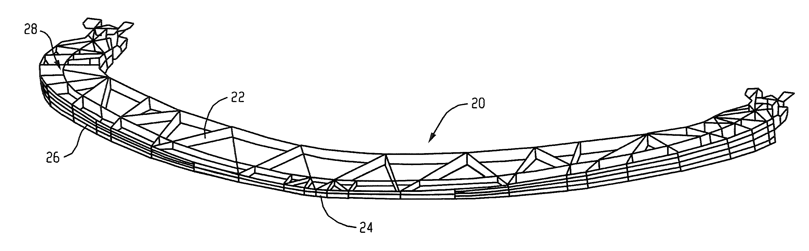
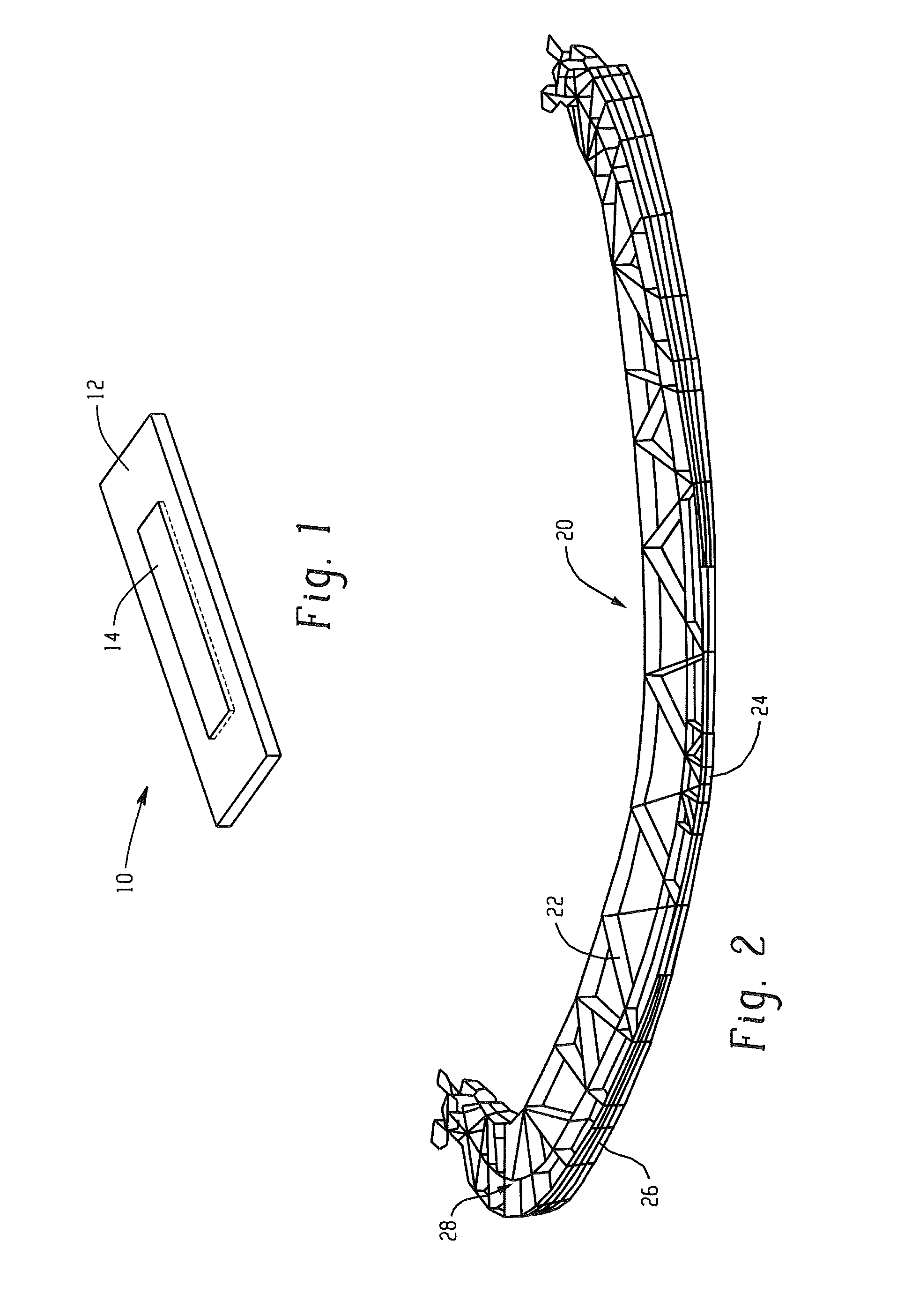
[0057]Table 1 illustrates the performance summary for lower leg impact on a generic vehicle platform with a lower spoiler design corresponding to FIG. 2. In Table 1, a lower spoiler made from glass filled polyimide (Sample 1) and a lower spoiler made from Xenoy® resin (Sample 2), neither comprising an insert were compared with an energy absorber made from Xenoy® resin comprising an insert (Sample 3) and an energy absorber comprising an insert that spanned the full width of the vehicle front (Sample 4). Sample 1 and 2 had no inserts, and Sample 3 had an insert at the center of the front face of lower spoiler (the insert had a height that was about 80% of the wall height and extended the full length of the outer wall), as is shown in FIG. 2.

[0058]The vehicle bumper system incorporating proposed lower spoiler is impacted with a commercially available lower leg model and a knee acceleration model, i.e., G-load in units of gravity (G), knee bending (i.e. rotation in ...

example 2

Vehicle Damageability

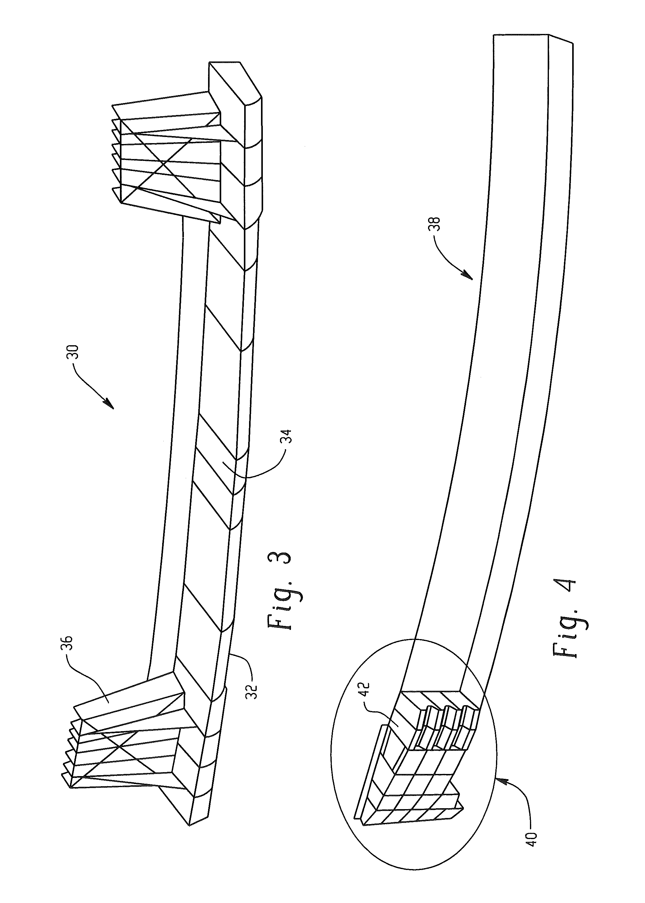
[0062]Table 3 illustrates the performance summary for an IIHS bumper like barrier with a 15% overlap on a generic vehicle platform with an injection molded corner energy absorber corresponding to FIGS. 4 and 5. Samples 7 and 8 were both injection molded. The corner energy absorber extended from both the end of a bumper beam. The corner energy absorber has an extension that extended into the end of the bumper beam (i.e., into the hollow portion of the bumper beam) as illustrated in FIG. 4. The energy absorbers in Samples 7 and 8 contained extensions on the ends of the energy absorbers designed to absorb energy upon impact. Sample 8 comprised inserts on the extensions. The inserts were set in the design illustrated in FIGS. 4 and 5. The vehicle bumper system incorporating a proposed corner energy absorber is impacted with a commercially available ‘Bumper like barrier for IIHS protocols’ and a Force in units of kiloNewtons (kN) and intrusion in millimeters (mm) are...

example 3

Dual Stage Energy Absorber

[0064]Tables 4 and 5 illustrate the performance summary for a Xenoy® resin energy absorber designed for global use for lower leg impact performance and low speed vehicle damageability on a generic vehicle platform, as described in U.S. Pat. No. 7,568,746. The maximum G load, maximum rotation, and maximum shear were measured as described above with respect to Samples 1 to 6. Each of Samples 9 to 12, 13, and 15 occupied 85 mm of packaging space, while Samples 14 and 16 only occupied 80 mm of packaging space. Samples 10, 12, 14, and 16 each contained an insert as shown in FIGS. 6 and 7, while Samples 9, 11, 13, and 15 did not. Y0 is the impact at center of the vehicle bumper along the width and Y264 is an impact 264 mm outboard from center of the vehicle.

TABLE 4CompositeSam-SystemInsertMax.Max.Max.pleWeightWeightGRotationShearNo.(kg)(kg)Load(Degree)(mm)Y-0 Impact Location9Xenoy ® resin0.92N / A141.5151.5Dual stage EA(85 mm)*10Dual stage EA0.920.025130.1151.5with...


PUM


Abstract

In one embodiment, an energy absorber, comprises: a plurality of crush lobes including a base and sides extending from the base to an outer wall; and a composite insert in the energy absorber. The insert comprises a second plastic material and reinforcement. The second plastic material is different than the crush lobe material. The insert is located at an area of the crush lobes, and wherein the area is the side and/or the outer wall. In another embodiment, an energy absorber comprises: a plastic frame; thermoplastic crush lobes extending from the frame, wherein the crush lobes comprise an outer wall, an extending wall, and a base; and a plastic insert located at an area having a volume of the crush lobes, wherein the insert occupies less than or equal to 90% of the area volume. The insert comprises reinforcement and a plastic material different than the thermoplastic crush lobes.

Description

BACKGROUND[0001]The present disclosure relates generally to energy absorbers for use in a vehicle, for example, to reduce injuries (e.g., to occupant(s), pedestrian(s), etc.) and / or to reduce vehicle damage.[0002]Increased importance has been placed on methods for minimizing the amount of injury suffered by a person during an impact with a moving vehicle as well as the amount of vehicle damage. Different regulatory committees assess automotive-pedestrian and occupant impact performance globally. Depending on the overall performance, vehicles are assigned a cumulative safety rating. Each and every component of the vehicle needs to satisfy the specific impact criteria in order to ensure a good overall rating for the vehicle.[0003]Due to the regulatory requirements and the desire to have, and commercial advantages of having, a high overall safety rating, vehicle manufacturers are continually adding components such as energy absorbers to the vehicle. Although energy absorbers generally ...

Claims


Application Information

Patent Timeline
IPC IPC(8): B60R19/03
CPCB60R19/18B60R2019/1853B60R2019/186F16F7/124B60R19/34F16F7/003B60R19/03
Inventor MARUR, SUDHAKAR RAMAMOORTHYNAGWANSHI, DHANENDRA KUMAR
Owner SABIC GLOBAL TECH BV
Why Eureka
Try Eureka