
Patsnap Eureka
For R&D, Patsnap Eureka makes reading and utilizing patents & technical documents easy.
Patsnap Eureka AIR
Designed for self-driven R&D workflows. Generate viable solutions, solve complex R&D challenges, empower your innovation with AI.

Patsnap Eureka Materials
Designed for material experts only. Revolutionize your material R&D, from search, analyze, to developing new materials.

TechResearch
Generate reliable direction feasibility study reports for your R&D in just a few steps.

TechSeek
Discover and master advanced knowledge NOW. Basics, ideas, possibilities, all at once.

TechMind
As an expert in R&D Theories, TechMind can generates customized viable solutions instantly.

TechRisk
Analyze your overall solution with one click, know your potential R&D risks in advance.

TechMonitor
Get weekly tech updates, stay abreast of the latest tech innovations and key insights.
Drive mechanism for a longwall mining machine
a technology of driving mechanism and mining machine, which is applied in the direction of slitting machine, mechanical equipment, sprocket arrangement, etc., can solve the problems of damage to haulage components, troublesome wear between the top and the driven sprocket, and insufficient low profile of the sprocket arrangemen
- Summary
- Abstract
- Description
- Claims
- Application Information
AI Technical Summary
Benefits of technology
Problems solved by technology
Method used
Image

Examples
Embodiment Construction
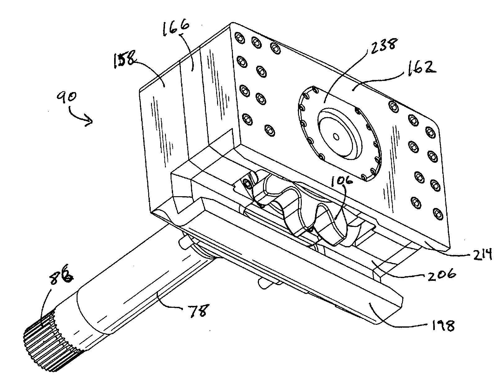
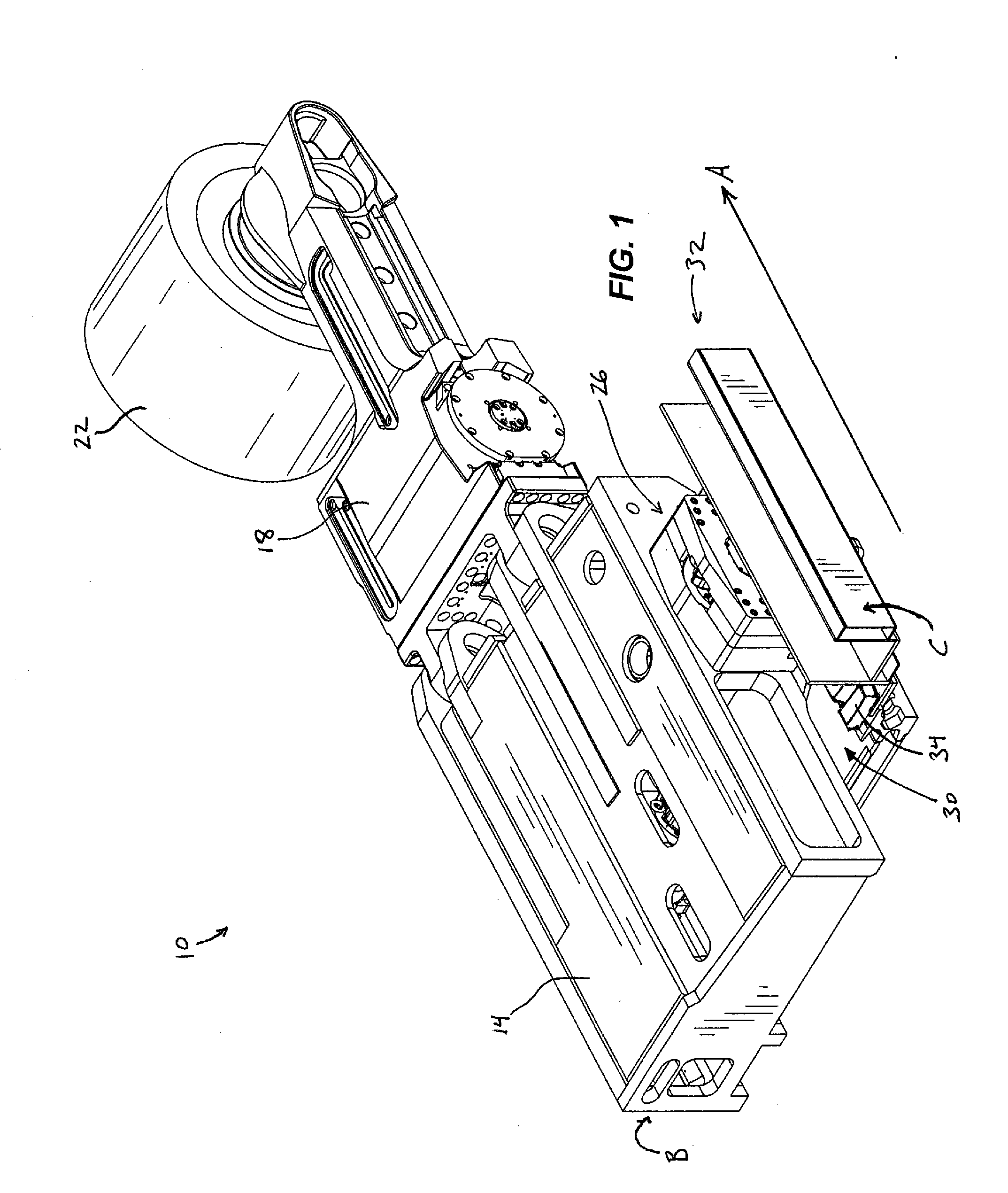
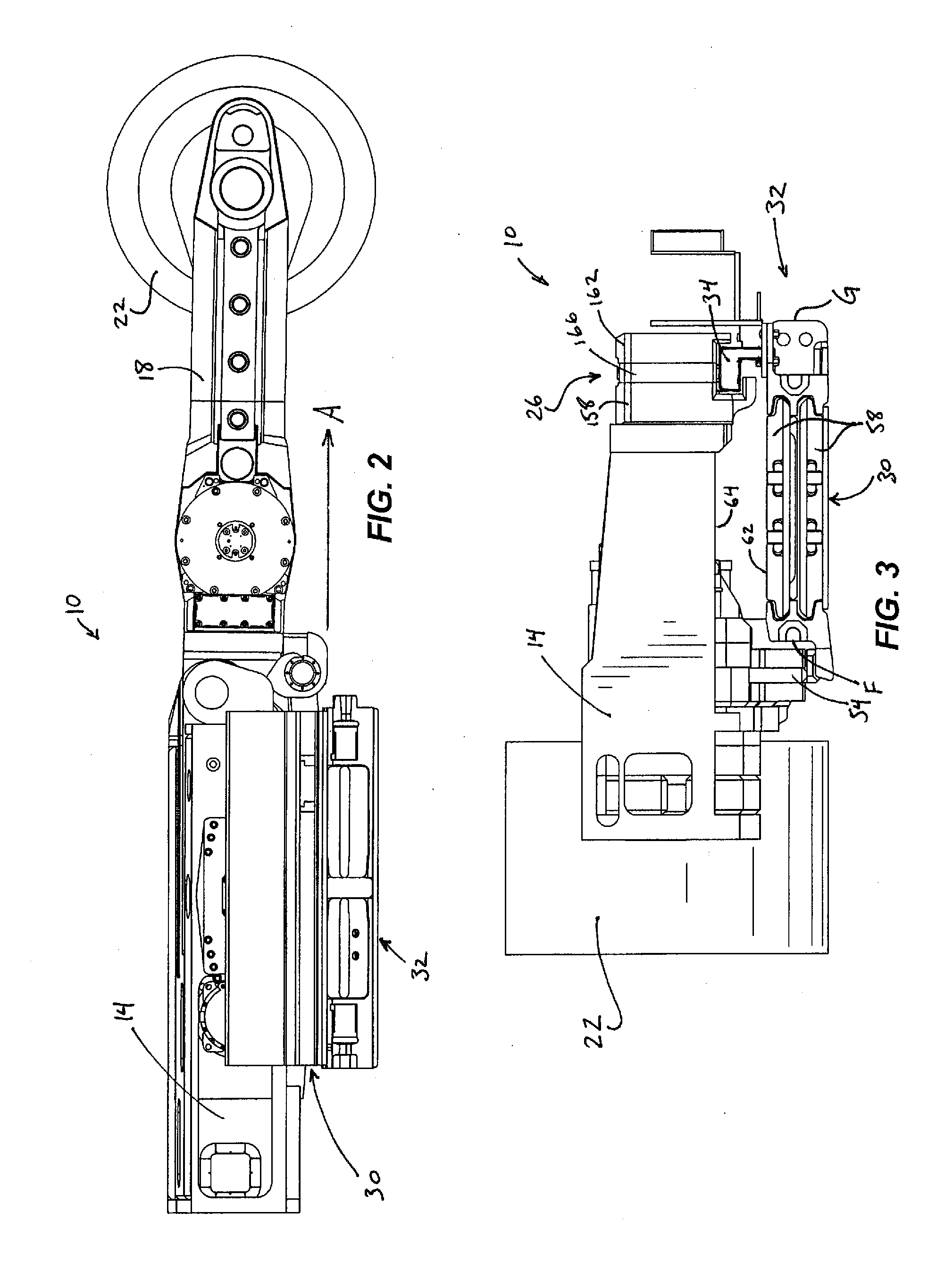
[0024]FIGS. 1-4 illustrate a mining machine, which is a longwall shearer 10, according to one construction of the invention. The shearer 10 includes a frame or body portion 14, a front or first cutter arm 18 pivotably connected to the body portion 14, and a front or first cutter head 22 rotatably coupled to the front cutter arm 18. The shearer 10 also includes a drive system 26 and a product removal system 30. Although not illustrated, in other constructions, the shearer 10 includes a rear or second cutter arm pivotably connected to the body portion 14 opposite the front cutter arm 18, a rear or second cutter head rotatably coupled to the second cutter arm, and second drive system is mounted to the body portion 14 near the second cutter arm. In other words, a double ended mining machine may have a cutting arm and head at a front end and at a back end (i.e., first and second ends) and two drive systems, one located at each end. Only one cutter arm and drive assembly will be described...
PUM
 Abstract
Description
Claims
Application Information
 - R&D Engineer
- R&D Manager
- IP Professional
- Industry Leading Data Capabilities
- Powerful AI technology
- Patent DNA Extraction
Browse by: Latest US Patents, China's latest patents, Technical Efficacy Thesaurus, Application Domain, Technology Topic, Popular Technical Reports.
© 2024 PatSnap. All rights reserved.Legal|Privacy policy|Modern Slavery Act Transparency Statement|Sitemap|About US| Contact US: help@patsnap.com