Hand-held power tool

a hand-held power tool and hand-held technology, applied in the direction of wrenches, metal-working apparatus, turner accessories, etc., can solve the problems of reducing affecting the ergonomics of operation, and comparatively large construction height, so as to improve the working field of hand-held power tools. optimally, simple design measures

Inactive Publication Date: 2012-05-03
ROBERT BOSCH GMBH
View PDF2 Cites 7 Cited by
  • Summary
  • Abstract
  • Description
  • Claims
  • Application Information

AI Technical Summary

Benefits of technology

[0004]An object of the present invention is to illuminate the working field of a h...

Problems solved by technology

A disadvantage here is the comparatively large construction height, which comes about due to the angular positioning of the lighting element relative to the tool axis.
The trigger switch for activating the electr...

Method used


Image

  • Hand-held power tool
  • Hand-held power tool
  • Hand-held power tool

Examples


Embodiment Construction

[0014]In the figures, identical components are given identical reference numerals.

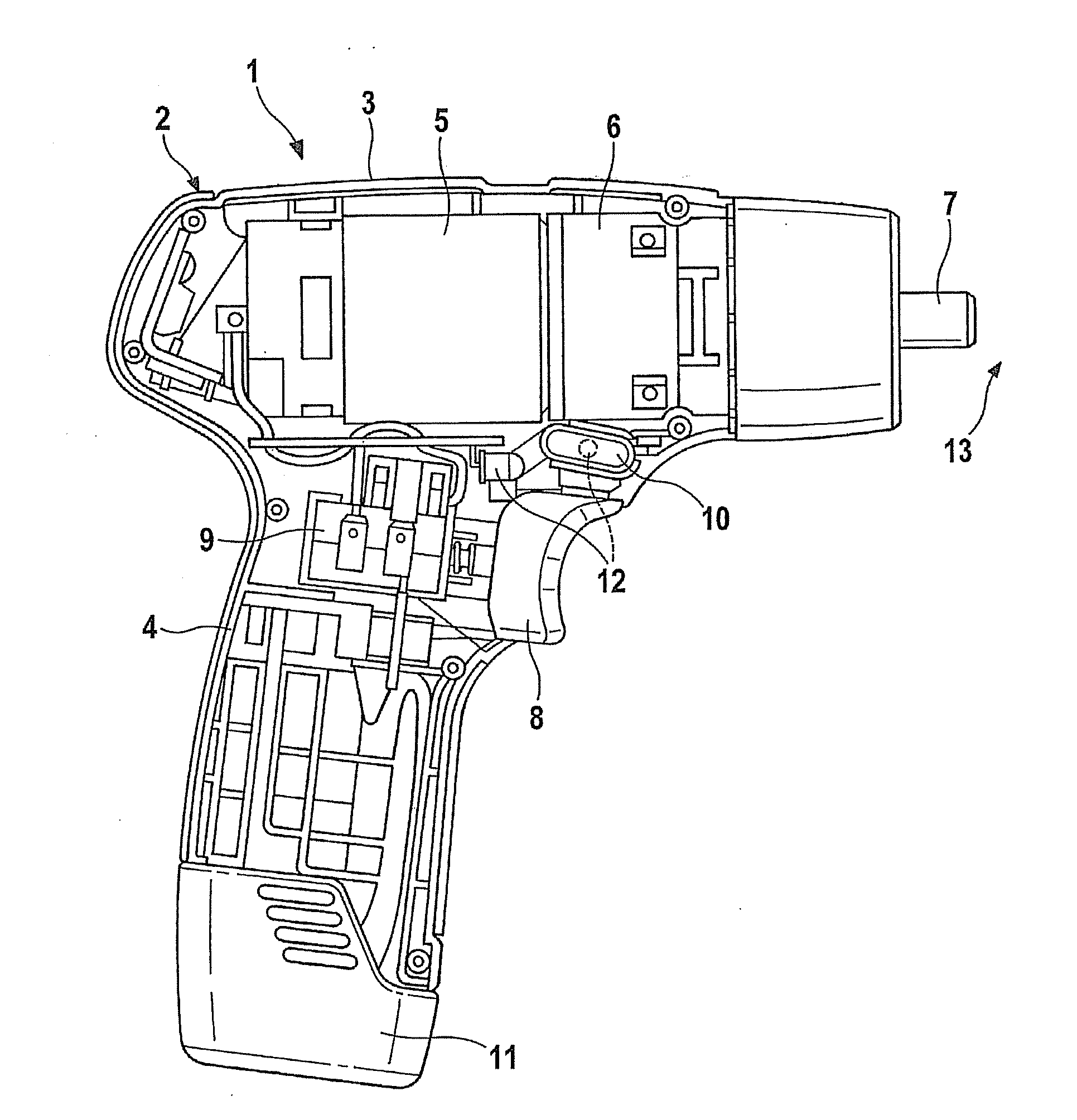
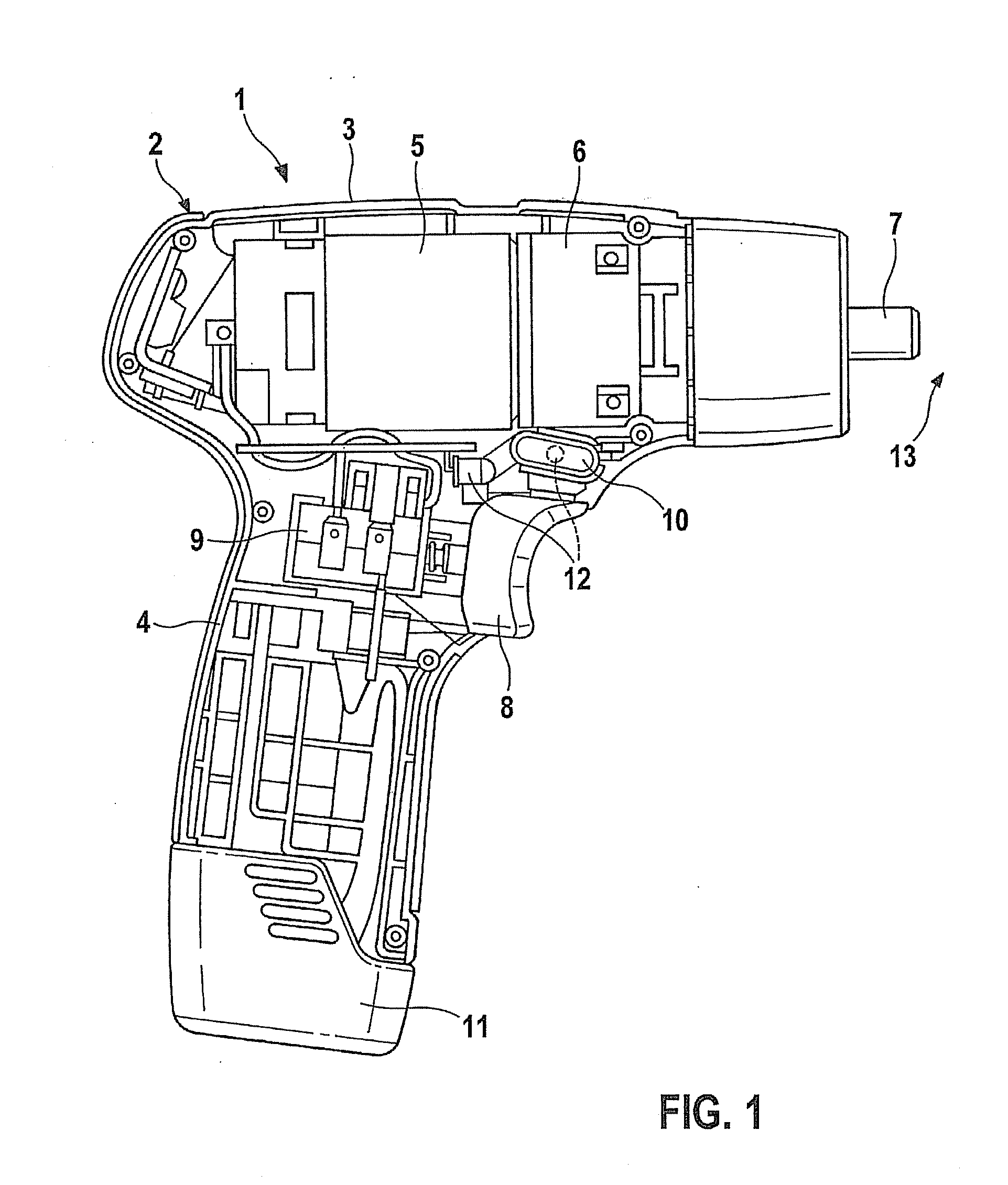
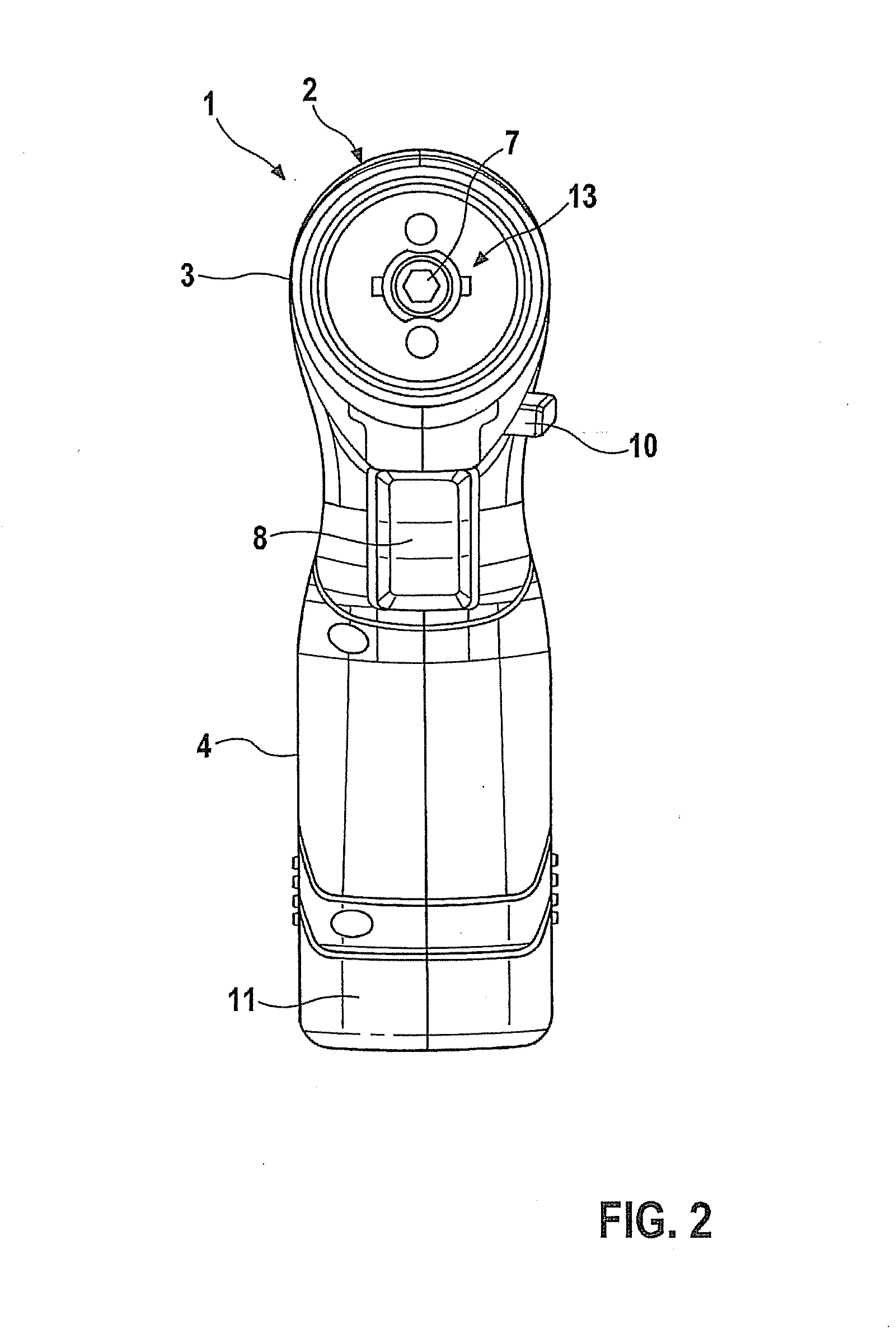
[0015]Hand-held power tool 1 shown in FIG. 1 has a housing 2, made up of a motor housing 3 and a grip housing 4 oriented approximately perpendicularly to motor housing 3, motor housing 3 and grip housing 4 possibly being designed as a single piece or as separate components. Contained in motor housing 3 is an electric drive motor 5 and also a gear unit 6, which is actuated by drive motor 5 and through which the drive motion is transferred to a spindle or tool-holding fixture 7 for receiving a tool. Gear unit 6 is, for example, a planetary transmission for converting the high motor speed to the lower speed of the tool-holding fixture.

[0016]Drive motor 5 is put into operation via a trigger switch 8, which is movable relative to the housing, and is located on grip housing 4, the speed of rotation of the drive motor being adjusted via the measure of actuation of trigger switch 8, which acts internally on a ...


PUM


Abstract

A hand-held power tool is equipped with a lighting element for illuminating the working field, the lighting element including a light source and a trigger switch for activating or adjusting a drive motor forming a component of the lighting element in such a way that light beams emitted by the light source are guided via the trigger switch to the working field.

Description

FIELD OF THE INVENTION[0001]The present invention relates to a hand-held power tool, in particular an electrically operated hand-held power tool such as a rechargeable screwdriver or rechargeable drill.BACKGROUND INFORMATION[0002]U.S. Pat. No. 7,185,998 B2 describes a rechargeable screwdriver or drill, which has an electric drive motor for driving a tool-holding fixture in a motor housing. Extending approximately perpendicularly to the motor housing is a grip housing, at the lower end of which a rechargeable battery pack for supplying power is situated. Situated in the area of transition between the rechargeable battery pack and the grip housing is a lighting element, which includes a light source having a lens placed in front of it, through which a light beam is emitted to the working field lying directly in front of the tool-holding fixture. Because of the comparatively large distance between the lighting element and the working field, the lighting element must have relatively hig...

Claims


Application Information

Patent Timeline
IPC IPC(8): B25B23/18B23B25/00
CPCB25B23/18B25F5/021
Inventor ROEHM, HEIKO
Owner ROBERT BOSCH GMBH
Why Eureka
Try Eureka