Sealing plate and rotor blade system

a sealing plate and rotor blade technology, applied in the direction of blade accessories, leakage prevention, machines/engines, etc., can solve the problems that other vacuum investment casting processes are not possible, and achieve the effect of reducing material use and costs, simple design, and low production and material costs

Inactive Publication Date: 2012-05-03
SIEMENS AG
View PDF17 Cites 6 Cited by
  • Summary
  • Abstract
  • Description
  • Claims
  • Application Information

AI Technical Summary

Benefits of technology

[0022]The advantages which are achieved using the invention are especially that as a result of the construction of the sealing plate by means of a multiplicity of metal sheets a particularly simple design and construction of the sealing plate become possible. The production costs and material costs are low in this case in comparison to other methods. As a result of the flexible material pairing, the material use and costs arising therefrom can be reduced. After-machining of the large plane surfaces—as is necessary in the case of the casting process—is not necessary when using preformed metal sheets, wherein a particularly good sealing effect of the sealing plate during operation is still achieved. As a result of this, and as a result of the active component cooling by means of conducting cooling air in the sealing plate, lower restrictions for the hot gas temperature in a gas turbine ensue and a higher efficiency can be achieved overall.

Problems solved by technology

In this case, casting processes other than the described vacuum investment casting are not a possibility on account of the selected materials for the sealing plates.

Method used


Image

  • Sealing plate and rotor blade system
  • Sealing plate and rotor blade system
  • Sealing plate and rotor blade system

Examples


Embodiment Construction

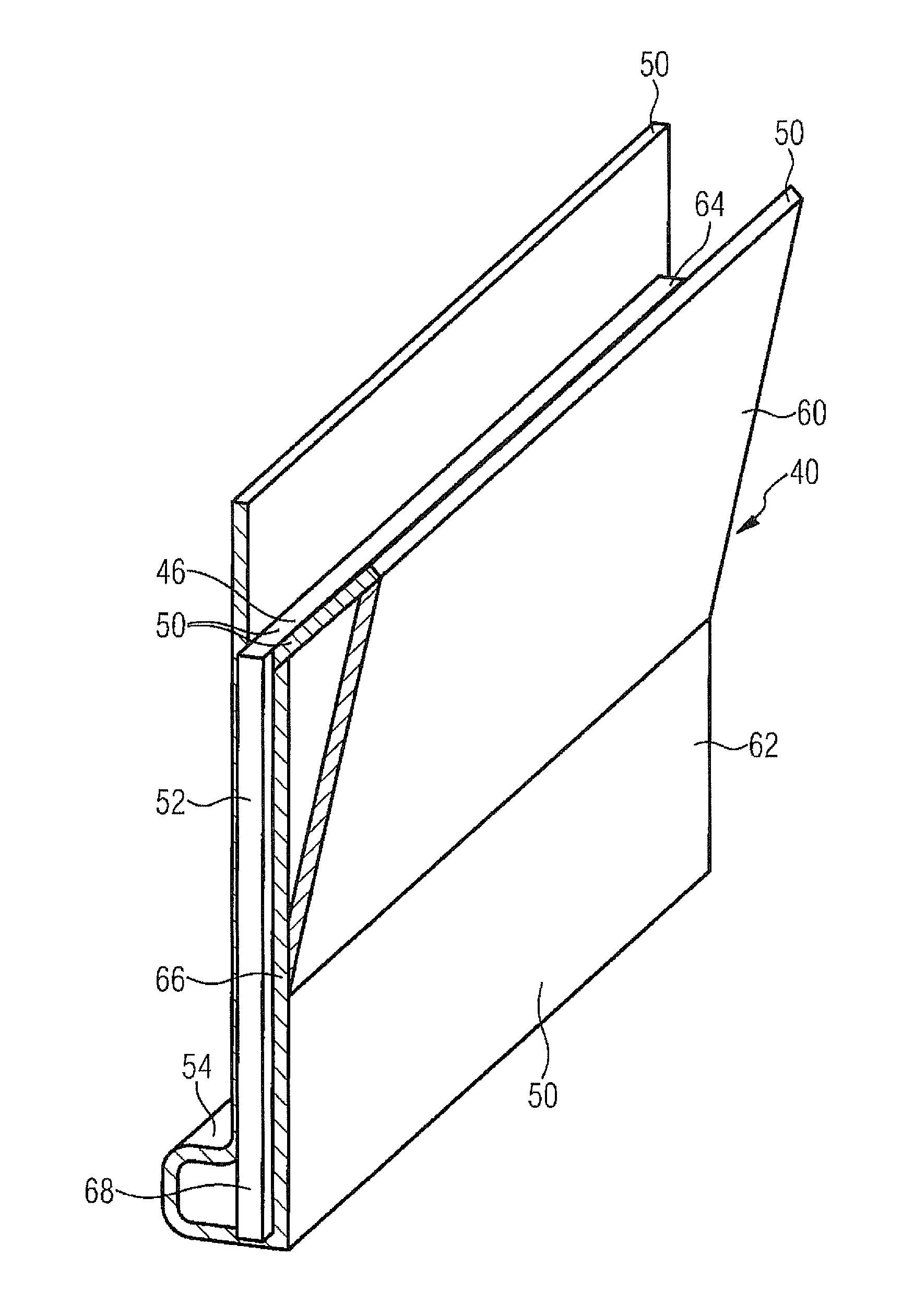
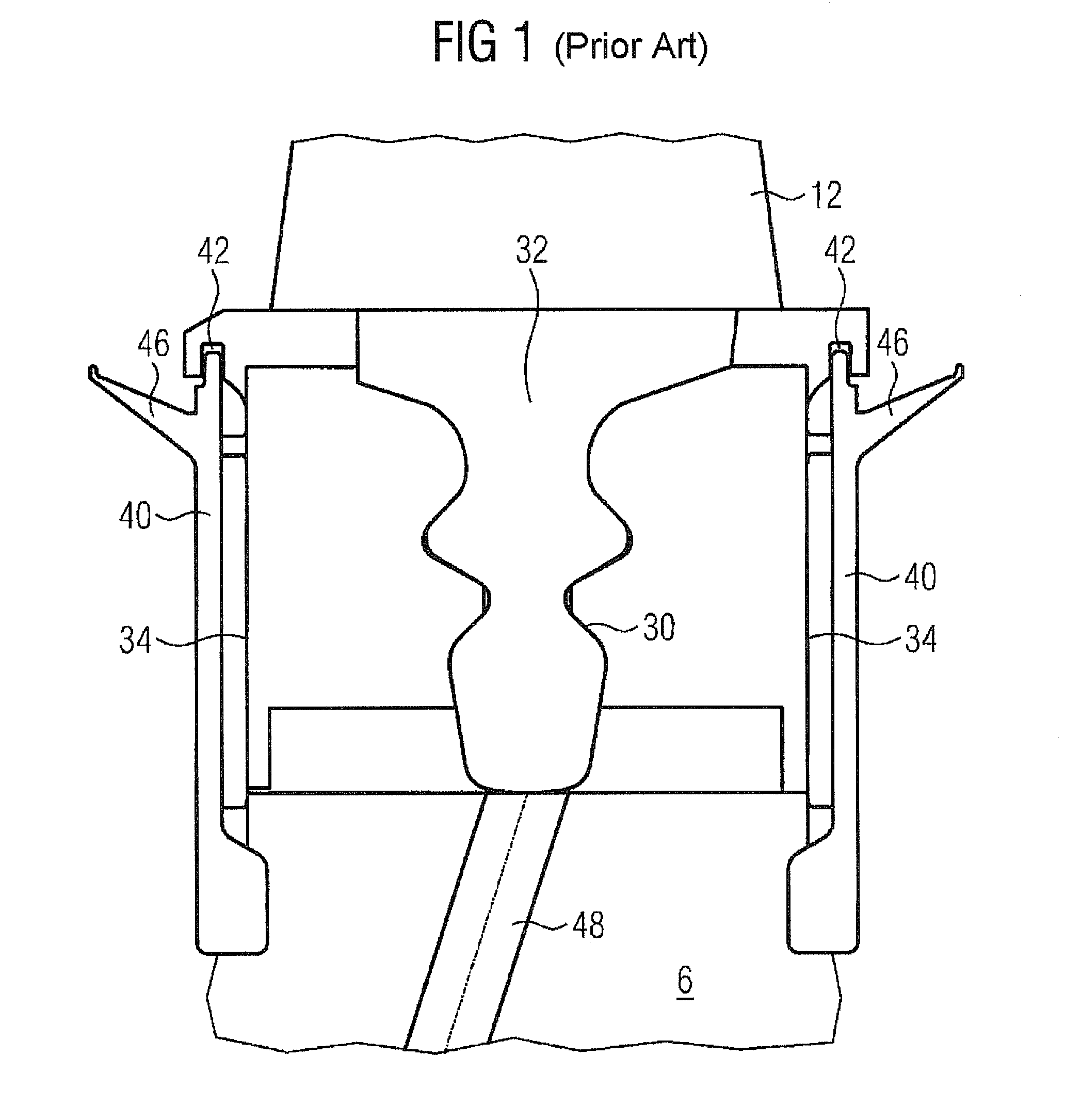
[0031]Like parts are provided with the same designations in all the figures.

[0032]FIG. 1 shows a rotor blade system 1 as a section through the outer circumference of a turbine disk 6, attached on a turbine shaft, of a rotor blade stage of a gas turbine according to the prior art.

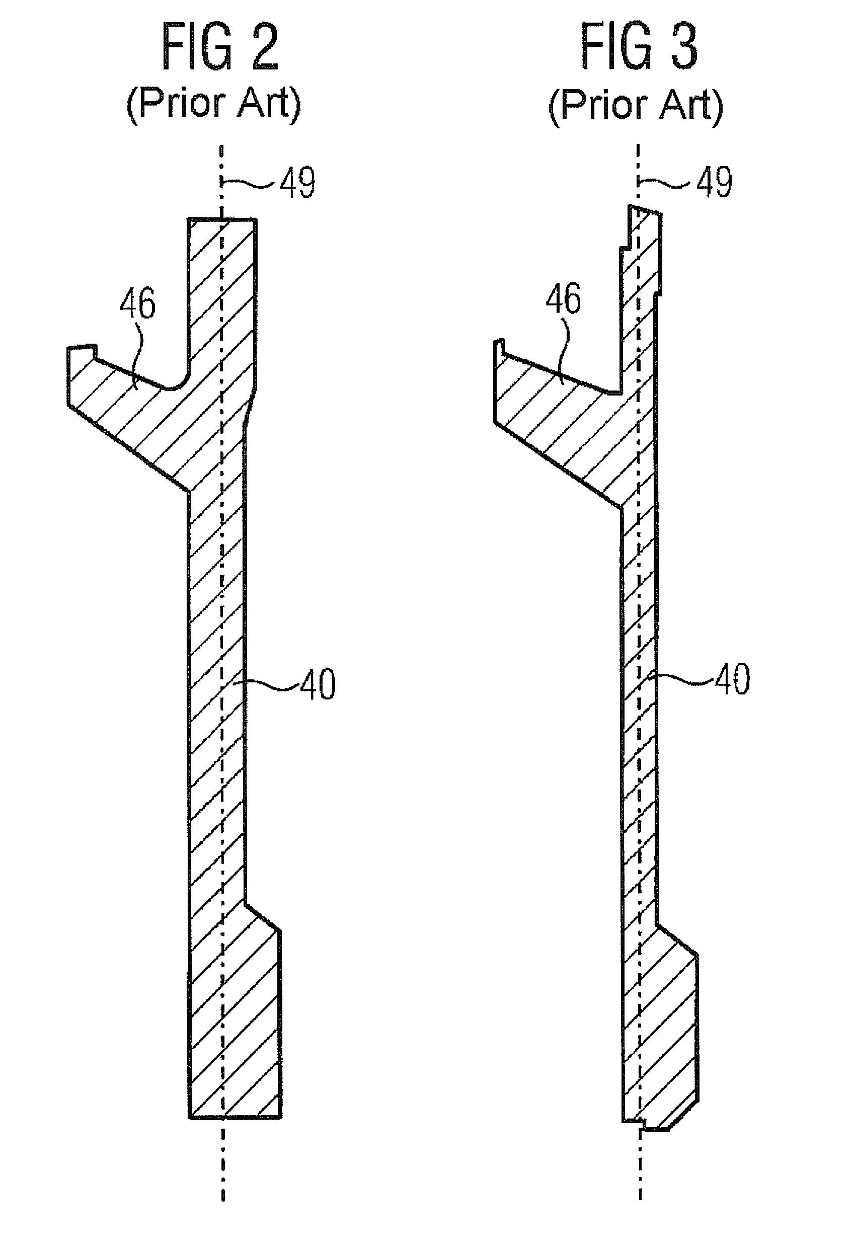
[0033]A rotor blade 12 is arranged in a rotor blade retaining slot 30 by its blade root 32 in this case. The blade root 32 of the rotor blade 12 is of a firtree shape in cross section and corresponds to the firtree shape of the rotor blade retaining slot 30. The schematic representation of the contour of the rotor blade root 32 and that of the rotor blade retaining slot 30 is reproduced in a manner rotated by 90° compared with the rest of the view of FIG. 2. Therefore, the depicted rotor blade retaining slot 30 extends between the side surfaces 34 of the turbine disk 6.

[0034]Adjacently provided in each case are stator blades 36, not shown in more detail, which are arranged upstream and downstream of the roto...


PUM


Abstract

A rotor blade system, for example, of a gas turbine is provided. The rotor blade system includes a plurality of rotor blades which are arranged annularly on a rotor disk. A plurality of sealing plates are arranged on a side surface of the rotor disk. An individual sealing plate is formed from a plurality of metal sheets, wherein two of the metal sheets are arranged opposite each other a distance apart and parallel to a plane of the sealing plate, forming a gap for guiding of cooling air.

Description

CROSS REFERENCE TO RELATED APPLICATIONS[0001]This application is the US National Stage of International Application No. PCT / EP2010 / 053917, filed Mar. 25, 2010 and claims the benefit thereof. The International Application claims the benefits of European application No. 09004469.4 filed Mar. 27, 2009. All of the applications are incorporated by reference herein in their entirety.FIELD OF INVENTION[0002]The invention refers to a sealing plate for forming a ring consisting of sealing plates for the rotor of a gas turbine, which sealing plate is formed principally from a multiplicity of metal sheets. In addition, the invention refers to a rotor blade system, especially for a gas turbine, having a number of rotor blades which are arranged annularly on a turbine disk, wherein a number of sealing plates are arranged on a side surface of the turbine disk. It furthermore refers to a gas turbine having such a rotor blade system.BACKGROUND OF INVENTION[0003]Gas turbines are used in many fields ...

Claims


Application Information

Patent Timeline
Patent Type & Authority Applications(United States)
IPC IPC(8): F01D5/08
CPCF01D5/3015F05D2230/232F01D11/005
Inventor BUCHAL, TOBIASDUNGS, SASCHAESSER, WINFRIEDGRUGER, BIRGITLUSEBRINK, OLIVERMILAZAR, MIRKOSAVILIUS, NICOLASSCHNEIDER, OLIVERSCHRODER, PETERSOCHA, WALDEMAR
Owner SIEMENS AG
Why Eureka
Try Eureka