Polyetherimide stitched reinforcing fabrics and composite materials comprising the same

Inactive Publication Date: 2012-05-03
GENERAL ELECTRIC CO +1
0 Cites 3 Cited by

AI-Extracted Technical Summary

Problems solved by technology

However, the process of employing prepreg tapes is not very cost effective.
However, it is noticed that the composites employing non-crimp fabric with polyester or nylon stitches are susceptible to microcrack formations induced by residual st...

Method used

[0017]The reinforcing fabric layer can include one or more layers of the woven or felted fibers. In one embodiment, the reinforcing fabric layer can be a braid, or a mat. In one embodiment, the reinforcing fabric layer may include a non-woven fabric of continuous fibers. Examples of the non-woven fibers include but not limited to spunbonding, spunlacing, or fabric mesh. Spunbonded fibers are produced from continuous fibers that are continuously spun and bonded thermally. Spunlaced fibers are prepared from continuous fibers that are continuously spun and bonded mechanically. In one embodiment, the reinforcing fabric layer can include a fiber that is a non-woven mesh fiber. In one embodiment, the reinforcing fabric layer is a non-crimp fabric. As used herein the term “non-crimp fabric” also referred to as “warp-knitted” or “directionally oriented structure fabric” (dos-fabric) refers to one or more layers of fibers laid on each other, and held in place by a secondary non-structural thread without formation of a crimp. In one embodiment, the non-crimp fabric may be unidirectional that is fibers may be oriented in a single direction. In another embodiment, the non-crimp fabric may be multi-axial wherein alternate layers of fibers may be placed in various directions such as 0°, 45°, 90° and −45° to produce a reinforcing fabric layer of optimal strength. When the layers of fibers are aligned at 0°, it refers to the fibers being aligned along the length of the fabric (also known as the “wrap direction”), while the fibers at the 90° layers would be aligned ...

Benefits of technology

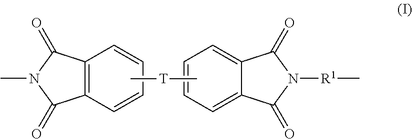
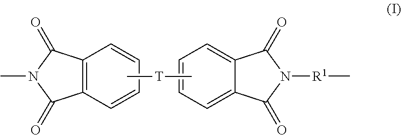
[0005]In one aspect, the present invention provides a preform, comprising: (a) a reinforcing fabric layer; and (b) a polyetherimide fiber incorporated into the reinforcing fabric layer as a stitch thread material, wherein the reinforcing fabric layer comprises less than about 10% by weight polyetherimide.
[0006]In another aspect, th...

Abstract

In one aspect, the present invention provides a preform, comprising: (a) a reinforcing fabric layer; and (b) a polyetherimide fiber incorporated into the reinforcing fabric layer as a stitch thread material. The reinforcing fabric layer comprises less than about 10% by weight polyetherimides. In another aspect, the present invention provides an uncured and a cured composite composition comprising the perform. Articles and method of making the cured composite compositions are also provided.

Application Domain

Layered productsWeight reduction +2

Technology Topic

FiberMaterials science +1

Image

  • Polyetherimide stitched reinforcing fabrics and composite materials comprising the same
  • Polyetherimide stitched reinforcing fabrics and composite materials comprising the same
  • Polyetherimide stitched reinforcing fabrics and composite materials comprising the same

Examples

  • Experimental program(1)

Example

Example 1
Preparation of Cured Composite Composition by Vacuum Assisted Resin Transfer Molding (VARTM) Process
[0040]Five to seven plies of the non-crimp fabric with polyetherimide stitches were layered and were sealed in a nylon vacuum bag film enclosure comprising a resin inlet and outlet under full vacuum (˜30 in Hg). A secondary bag was used to ensure a proper vacuum seal. RTM6 epoxy resin (from Hexcel, Dublin, Calif.) was heated to 80° C. and degassed under vacuum in a feed chamber. Prior to infusion, the vacuum on the feed chamber was reduced to ˜10 in Hg. The resin infusion into the fiber structure was started and the infusion was typically run at a temperature of 90° C. Resin flow was monitored during the infusion process which required about 30 minutes at the end of which time the resin was observed on the vacuum outlet to eliminate the air voids in the panel. Both inlet and outlet tubes were pinched off using Stapla tube sealer in order to maintain the high level of vacuum in the assembly. The resin-filled assembly was cured at 180° C. for 2 under vacuum to provide a void-free panel comprising the cured composite composition.
COMPARATIVE EXAMPLES
[0041]Comparative examples (CEx.1 and CEx.2) were prepared using the process described above except that the non-crimp fabric used comprised nylon stitches in the case of CEx.1 while the non-crimp fabric comprised polyester stitches in the CEx.2.
Method 2: Thermal Shock Cycling and Microcrack Analysis
[0042]After infusion, the composite parts were cut with a water jet and subjected to thermal shock cycling. The thermal shock chamber consisted of two compartments each maintained at a temperature of about 71° C. and a temperature of about −54° C. respectively. The parts were placed in each of the thermal shock chambers for a duration of five minutes, which constituted one cycle. The parts were subjected to about 400 to 2000 such cycles. Following the treatment in the thermal shock chambers, the treated parts were checked under an optical microscope for the presence of microcracks. The microcracks formed were analyzed using an optical microscope with a magnification of 50× and automated image analysis software. The microcrack number and lengths were determined in a total cross-section of 5.5″ by ⅛″.
TABLE 1 % Stitch Thread (as a % of the Stitch Stitch Thread weight of the Thread Diameter fiber mat, or Performance Entry Material (μm) equivalent) Rating Ex-1 PEI 90-100 <0.5 +++ CEx. 1 Nylon 100-150 <0.5 −−− CEx. 2 PET 150 <0.5 −−− (polyester) +++ = fewer than 5 microcracks after 2000 cycles; −−− = more than 50 microcracks after 2000 cycles
[0043]The data from Table 1 shows that the composites with the polyetherimide stitches did not show any microcrack even after thermal shock treatment for 2000 thermal cycles. While the composites of CEx.1 and CEx.2 displayed microcrack formation when subjected to thermal shock treatment of 400 thermal cycles. Additionally, it was also observed that the polyetherimide offers good compatibility with epoxy resins than polyesters and nylons. Furthermore, the glass transition temperature of the polyetherimide fibers (Tg>210° C.) is higher than the curing temperature (˜180° C.) for most aerospace rated epoxy systems resulting in the polyetherimide stitches having a lower coefficient of thermal expansion during curing process, thereby, contributing less residual stress within resin pocket area where stitches located and leading to a microcrack resistant composite composition. The cured composite compositions provided by the present invention exhibit excellent microcrack resistance under thermal humidity cycles (Ex. 1).
[0044]The foregoing examples are merely illustrative, serving to exemplify only some of the features of the invention. The appended claims are intended to claim the invention as broadly as it has been conceived and the examples herein presented are illustrative of selected embodiments from a manifold of all possible embodiments. Accordingly, it is the Applicants' intention that the appended claims are not to be limited by the choice of examples utilized to illustrate features of the present invention. As used in the claims, the word “comprises” and its grammatical variants logically also subtend and include phrases of varying and differing extent such as for example, but not limited thereto, “consisting essentially of” and “consisting of.” Where necessary, ranges have been supplied; those ranges are inclusive of all sub-ranges there between. It is to be expected that variations in these ranges will suggest themselves to a practitioner having ordinary skill in the art and where not already dedicated to the public, those variations should where possible be construed to be covered by the appended claims. It is also anticipated that advances in science and technology will make equivalents and substitutions possible that are not now contemplated by reason of the imprecision of language and these variations should also be construed where possible to be covered by the appended claims.

PUM

PropertyMeasurementUnit
Temperature20.0°C
Temperature140.0°C
Percent by mass10.0mass fraction

Description & Claims & Application Information

We can also present the details of the Description, Claims and Application information to help users get a comprehensive understanding of the technical details of the patent, such as background art, summary of invention, brief description of drawings, description of embodiments, and other original content. On the other hand, users can also determine the specific scope of protection of the technology through the list of claims; as well as understand the changes in the life cycle of the technology with the presentation of the patent timeline. Login to view more.
Why Eureka
Try Eureka