Heat Exchanger and Battery Unit Structure for Cooling Thermally Conductive Batteries

a technology of thermally conductive batteries and heat exchangers, which is applied in the direction of batteries, lighting and heating apparatus, electrical apparatus, etc., can solve the problems of more limited cooling effects, high cost of known methods for cooling batteries, and difficulty in recovering heat for use in other vehicle systems

Active Publication Date: 2012-05-03
DANA CANADA CORP
View PDF8 Cites 96 Cited by
  • Summary
  • Abstract
  • Description
  • Claims
  • Application Information

AI Technical Summary

Problems solved by technology

As well, this method has more limited cooling effects and also makes it more difficult to recover heat for uses in other vehicle systems.
Accordingly, known methods for cooling batteries tend to have high costs, increased space and / or weight penalties, as well as high tolerance requirements, all of which are desirable to overcome.

Method used


Image

  • Heat Exchanger and Battery Unit Structure for Cooling Thermally Conductive Batteries
  • Heat Exchanger and Battery Unit Structure for Cooling Thermally Conductive Batteries
  • Heat Exchanger and Battery Unit Structure for Cooling Thermally Conductive Batteries

Examples


Embodiment Construction

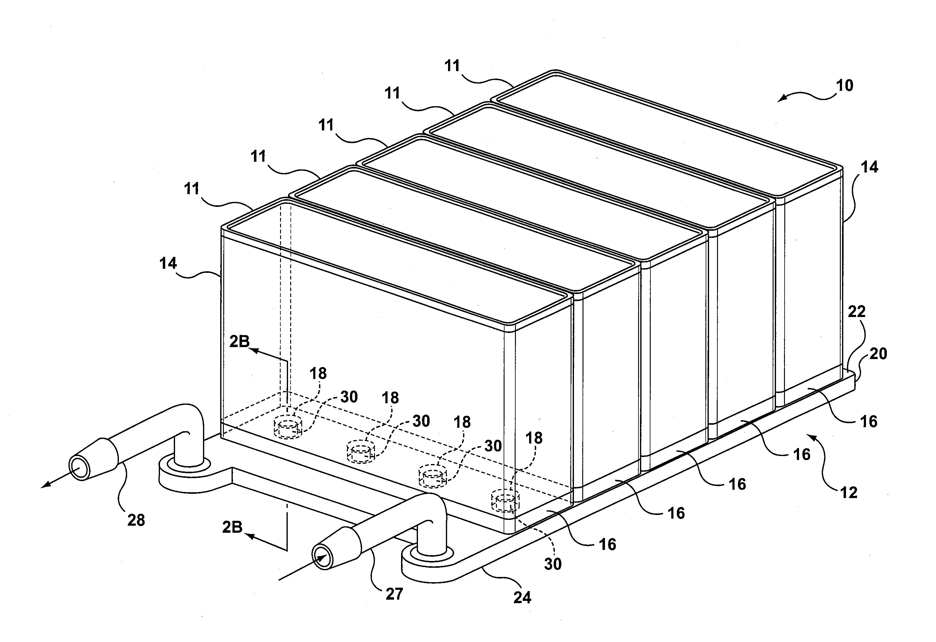
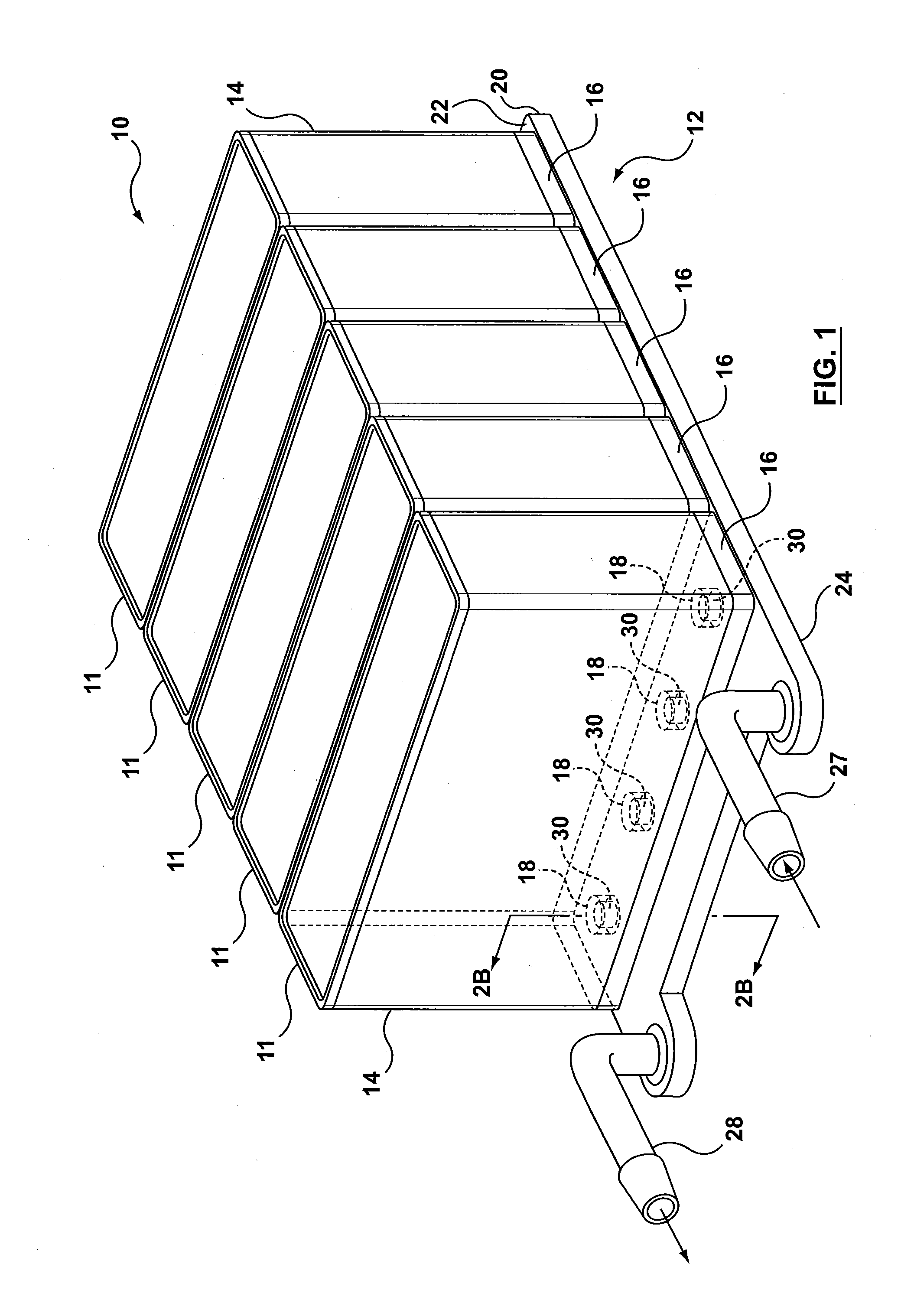
[0034]Referring now to the drawings, FIG. 1 shows a module 10 comprising five battery units 11 and a heat exchanger structure 12, according to one example embodiment of the present disclosure. While five battery units 11 have been shown, it will be understood that the subject embodiment is not intended to be limited to five battery units and that the heat exchanger structure 12 may be adapted to accommodate more or less battery units 11, depending upon the particular application of the device.

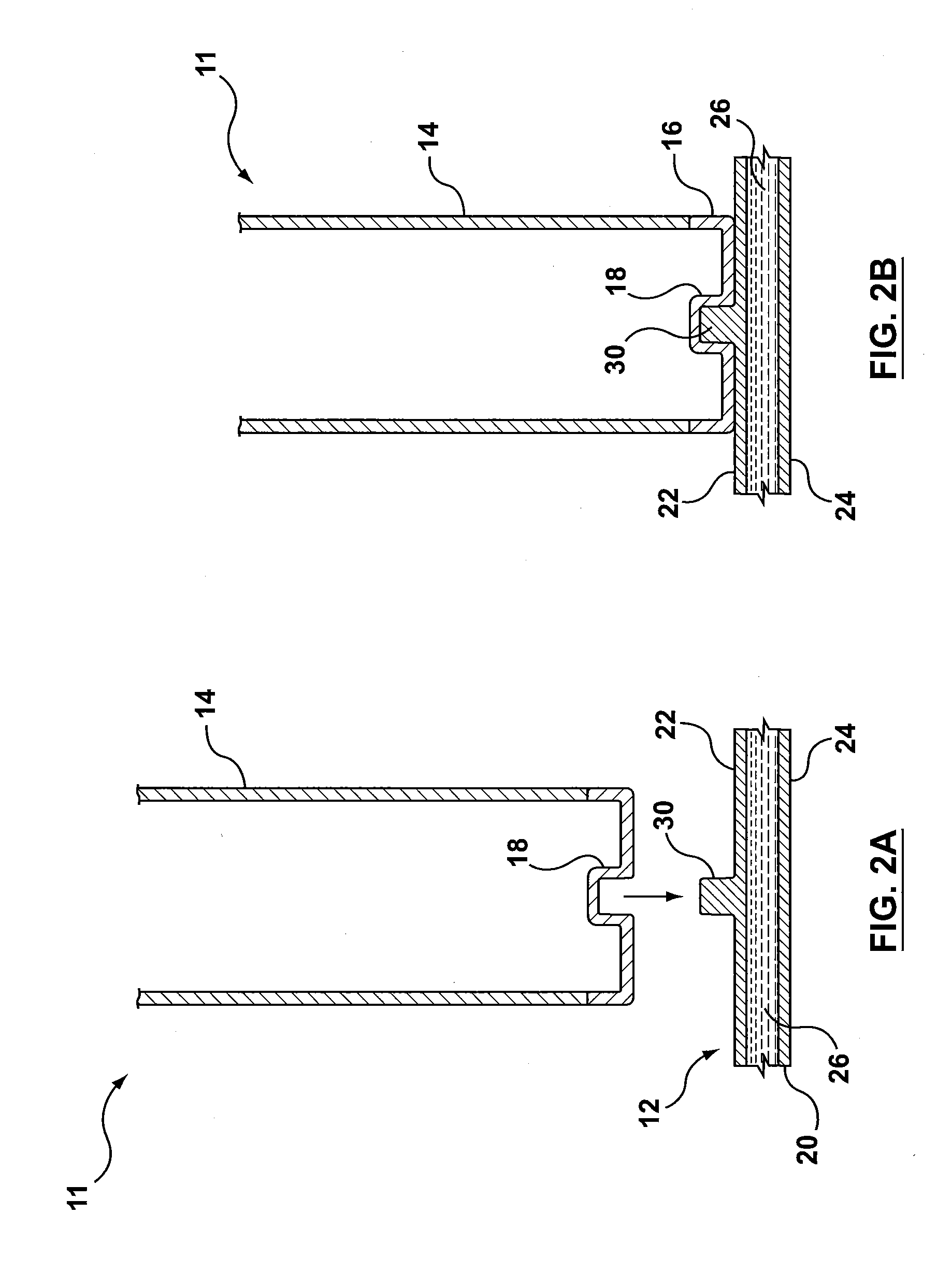
[0035]As shown, each battery unit 11 comprises an outer case or housing 14 that houses the internal components (not shown) of the battery unit 11, as is known in the art. In the subject embodiment, the outer housing 14 is constructed on a welded or an extruded base portion 16 having a first engaging device formed therein. In some embodiments, the base portion 16 may be formed of aluminum or steel and may be impact formed or formed as a welded assembly. In the embodiment shown, the first engagin...


PUM

PropertyMeasurementUnit
flexibleaaaaaaaaaa
electrochemicalaaaaaaaaaa
electrical impedanceaaaaaaaaaa

Abstract

A heat exchanger and battery unit structure is provided for cooling battery units (or cells) where the thermally conductive nature of the battery forms a cooling path. The heat exchanger is in the form of a cooling element provided with an engaging device formed on or attached to an outer surface of the cooling plate for receiving and/or engaging with a corresponding engaging portion on a battery unit (or cell). The interconnection between the battery unit (or cell) and heat exchanger creates a mechanical interlock between the two components that results in improved heat transfer properties between the two components.

Description

CROSS REFERENCE TO RELATED APPLICATION[0001]The present application claims priority to U.S. provisional application Ser. No. 61 / 407,972 filed on Oct. 29, 2010, which is currently pending and incorporated by reference in its entirely herein.TECHNICAL FIELD[0002]The present disclosure relates generally to the cooling of thermally conductive batteries by mechanical interlock.BACKGROUND[0003]Different types of battery cells, such as a round cell, a prismatic cell or a pouch cell are known. In the case of a round cell or a prismatic cell, the active material, containing the electrodes and separators, is generally rolled up into a coil and placed in a robust aluminum housing. In the case of the pouch cell, the individual layers of the active material are stacked or folded, and packaged into a flexible aluminum composite film.[0004]In operation, a current flow, either a charge or discharge, generates heat due to both electrochemical and electrical impedance effects. Due to temperature limi...

Claims


Application Information

Patent Timeline
Patent Type & Authority Applications(United States)
IPC IPC(8): H01M10/50
CPCF28F3/06H01M10/6556H01M10/6568H01M10/643H01M10/6565H01M2220/20H01M10/625H01M10/647H01M10/6551F28F3/12H01M10/613Y02E60/10F28D21/00F28F3/08
Inventor BURGERS, JOHN G.MARTIN, MICHAEL A.
Owner DANA CANADA CORP
Why Eureka
Try Eureka