
Front-loadable track mounting systems

Inactive Publication Date: 2012-05-10
HUNTER DOUGLAS INDS SWITZERLAND
View PDF10 Cites 29 Cited by
  • Summary
  • Abstract
  • Description
  • Claims
  • Application Information

AI Technical Summary

Benefits of technology

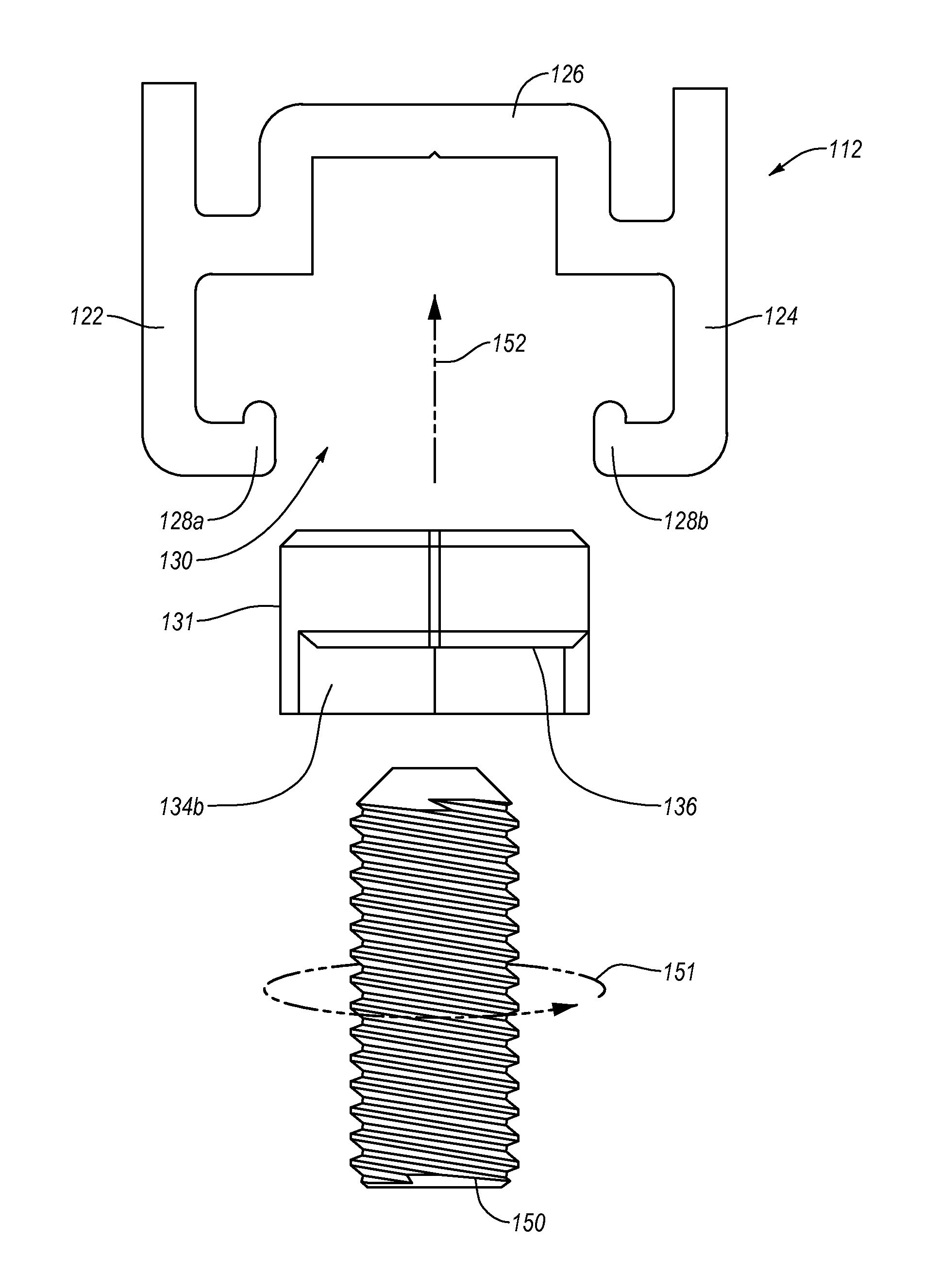
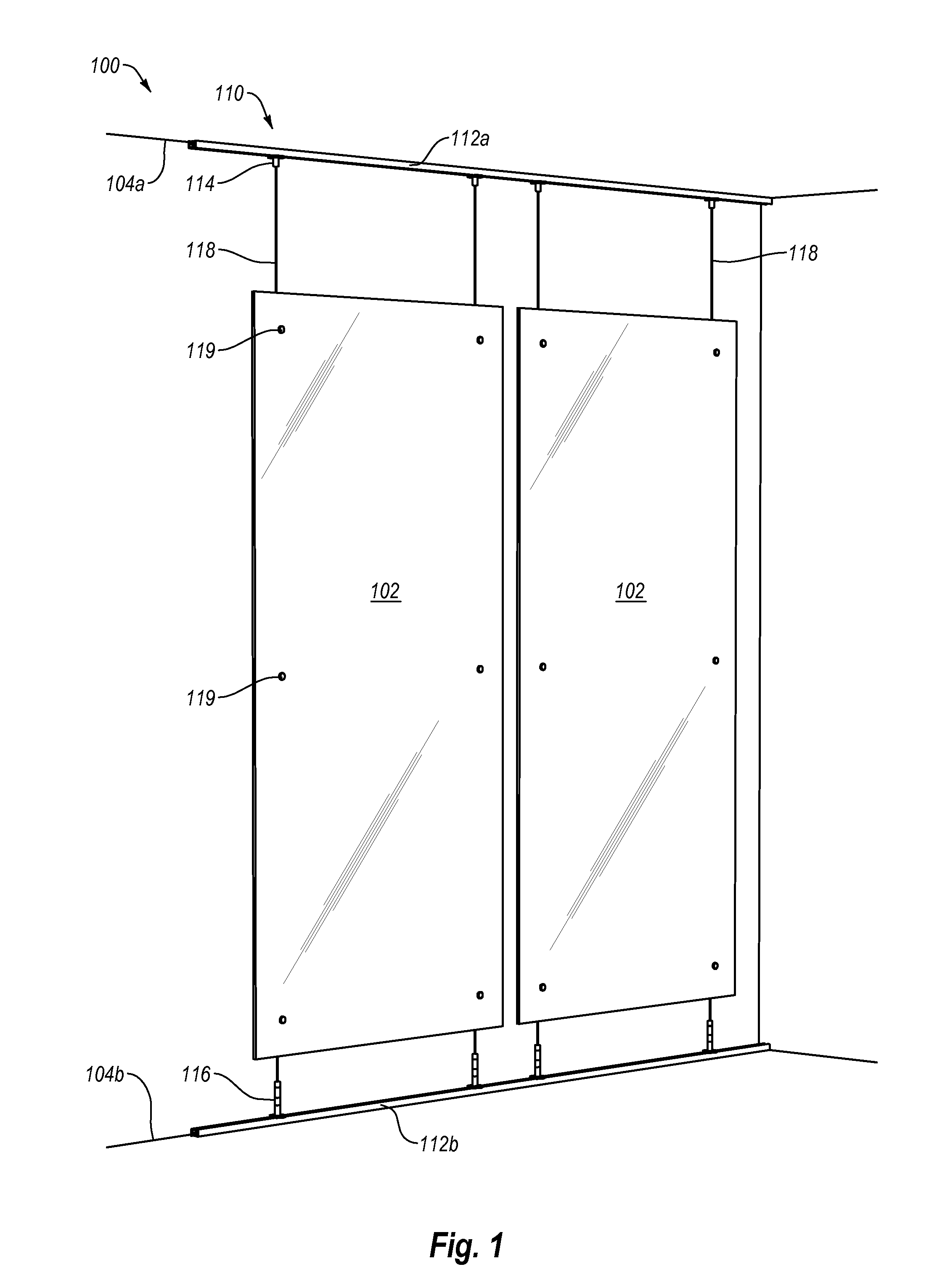
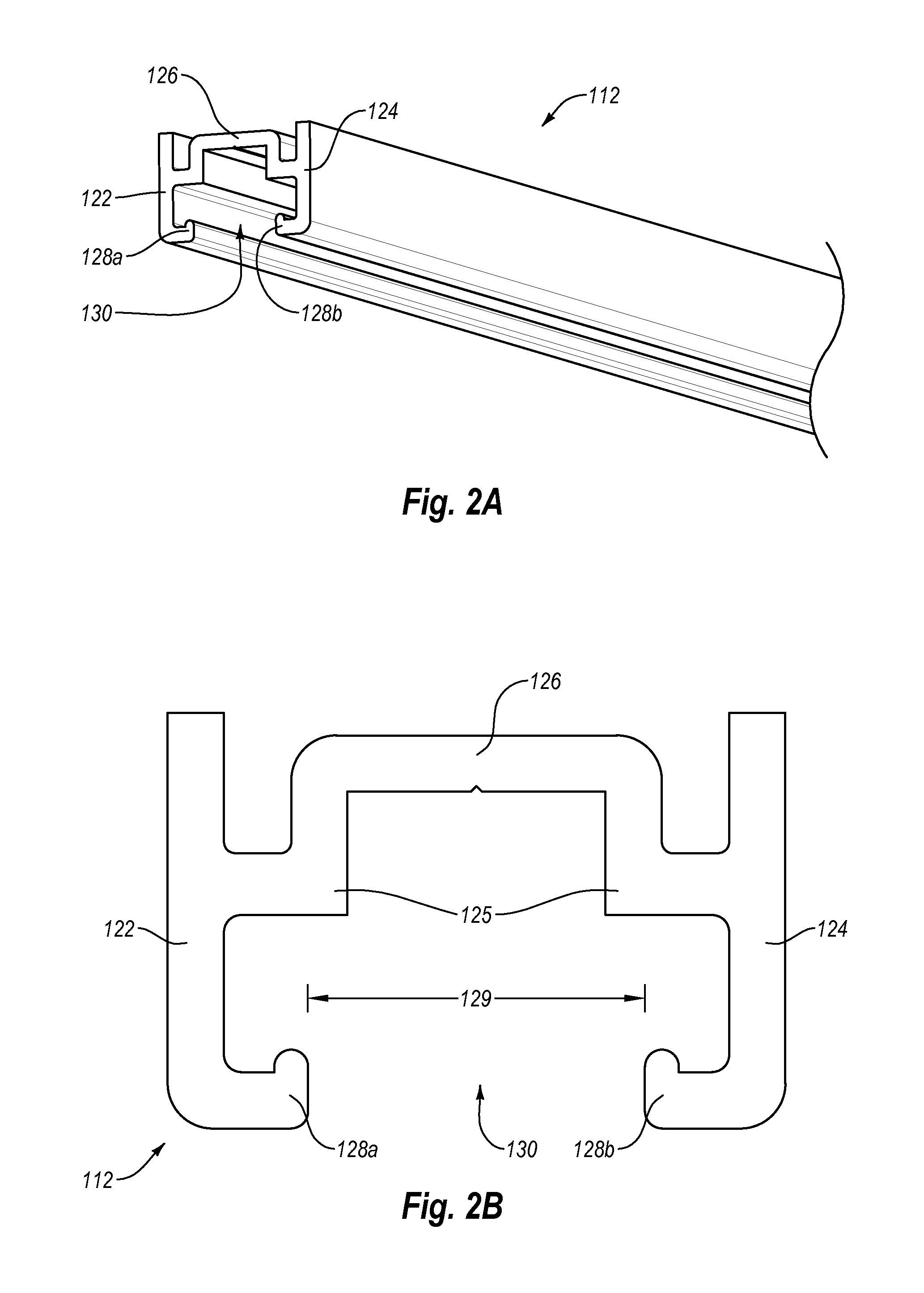
[0011]One or more implementations of the present invention solve one or more of the forgoing, or other, problems in the art with systems, methods, and apparatus for mounting or suspending panels that a user can easily adjust and configure for a wide variety of design environments. For example, one or more implementations of the present invention include a front-loadable track mounting system having mounting hardware that a user can insert anywhere along a front opening of the track. Thus, a user need not have to insert the mounting hardware into the ends of the track. In particular, the user can selectively insert, position, and lock a mounting nut within the track, and secure a wide variety of mounting components to the mounting nut. Accordingly, implementations of the present invention can allow a user to easily adapt the front-loadable track mounting system to the environment of use and provide a number of secure mounting options.

Problems solved by technology

Unfortunately, conventional panel mounting systems, such as these, tend to suffer from a number of drawbacks.
Aligning the anchor holes, however, can be difficult in many design environments.
Compounding this problem is the fact that once drilled, making adjustments to the anchor holes can be difficult, time consuming, or even impossible.
Misalignment of cables or standoffs may cause unwanted stress on panels mounted thereto.
Stress caused by mounting panels to misaligned cables or standoffs can cause panels to crack or otherwise damage the panels.
While conventional track systems can help reduce or minimize the misalignment of cables, conventional track systems may present other drawbacks.
Furthermore, in some design environments, the ends of the track may not be accessible after the installation of the track.
In such cases it may be difficult, time consuming, or impossible to change the mounting hardware, or reconfigure any mounted panels.
This same ability to freely move within a track, however, can lead to movement cables or panels mounted to the track via the mounting hardware.
As mentioned previously, movement in the mounting hardware can cause undesirable stresses in any panels mounted to the track.

Method used


Image

  • Front-loadable track mounting systems
  • Front-loadable track mounting systems
  • Front-loadable track mounting systems

Examples


Embodiment Construction

[0027]Implementations of the present invention provide systems, methods, and apparatus for mounting or suspending panels that a user can easily adjust and configure for a wide variety of design environments. For example, one or more implementations of the present invention include a front-loadable track mounting system having mounting hardware that a user can insert anywhere along a front opening of the track. Thus, a user need not have to insert the mounting hardware into the ends of the track. In particular, the user can selectively insert, position, and lock a mounting nut within the track, and secure a wide variety of mounting components to the mounting nut. Accordingly, implementations of the present invention can allow a user to easily adapt the front-loadable track mounting system to the environment of use and provide a number of secure mounting options.

[0028]In particular, one or more implementations include a track and a mounting nut that a user can selectively load into a ...


PUM

PropertyMeasurementUnit
Distanceaaaaaaaaaa

Abstract

A front-loadable track mounting system can include a track and mounting nut. The mounting nut and track can include corresponding features that allow a user to insert the mounting nut into a front opening in the track, and selectively lock the mounting nut in a desired position along the track. For example, the track can include opposing rails extending into the front opening of the track. The mounting nut can include that one or more ribs configured to rotate against the opposing rails of the track, and thereby, rotatably lock the mounting nut relative to the track.

Description

CROSS-REFERENCE TO RELATED APPLICATIONS[0001]The present invention is a US National Stage Application corresponding to PCT application No. PCT / US10 / 41028, filed on Jul. 6, 2010, which claims the benefit of priority to U.S. Provisional Application No. 61 / 223,626, filed Jul. 7, 2009, entitled “Front Loadable Track System and Mounting Nut.” The entire content of each of the foregoing applications is incorporated by reference herein.BACKGROUND OF THE INVENTION[0002]1. The Field of the Invention[0003]This invention relates to apparatus, systems, and methods for suspending or mounting panels from a support structure as partitions, displays, barriers, treatments, or other structures.[0004]2. Background And Relevant Art[0005]Some recent architectural designs are now implementing synthetic, polymeric resins, which are used as partitions, walls, decor, etc., in offices and homes. In general, resin materials such as these are now popular compared with decorative cast or laminated glass materia...

Claims


Application Information

Patent Timeline
IPC IPC(8): E05D15/00B23P11/00
CPCE04B2/7405F16B37/045G09F7/18Y10T16/373G09F15/0068Y10T29/49826G09F15/0006E04F13/0817E04B2/821
Inventor CHEN, SU-WEN
Owner HUNTER DOUGLAS INDS SWITZERLAND
Learn More