Rotary electric shaver and manufacturing method of outer cutter and inner cutter of the same

a technology of electric shaver and manufacturing method, which is applied in the direction of metal working apparatus, etc., can solve the problems of poor machining efficiency, uneven skin surface, and increased chances of unshaved areas, so as to improve shaving efficiency, smooth shave the concave portion, and improve shaving efficiency

Inactive Publication Date: 2012-05-10
IZUMI PROD CO
View PDF21 Cites 15 Cited by
  • Summary
  • Abstract
  • Description
  • Claims
  • Application Information

AI Technical Summary

Benefits of technology

[0021]According to the first aspect of the present invention, the plurality of concentric annular shaving sections or faces is formed on the upper surface of the outer cutter, so that the shaving area is increased to permit improved shaving efficiency. Further, the outer annular shaving section (adjacent to the outer periphery) is low, while the inner annular shaving section (adjacent to the center) is high. This allows all the annular shaving sections to precisely trace the curved surface of a concave portion of skin and to come in contact with the skin surface with an optimum contact pressure, thus making it possible to smoothly shave the concave portion.
[0022]A flat or convex portion of the skin can be smoothly shaved by applying mainly the inner annular shaving section thereto or tilting the entire electric shaver so as to tilt the upper surface (shaving section) thereof with respect to the skin. Further, the respective annular shaving sections are positioned on planes which are horizontal relative to the central axis and the heights of which differ toward the central axis. This simplifies the structures of the outer cutters and the inner cutters, reduces the number of components, and ensures easy assembling. Moreover, hair debris can be easily removed.
[0023]According to the second aspect of the present invention, the plurality of the annular shaving sections and the annular groove thereamong are formed in the metal sheet, which serves as the outer cutter, and the grinding / abrading tool with steps is relatively rotated concentrically with central axis of the outer cutter to grind / abrade the upper and lower surfaces of the outer cutter, thus making the machining easier.
[0024]According to the third aspect of the invention, the small blades that slidably contact with the plurality of annular shaving sections from below are integrally formed on the metal sheet constituting the inner cutter, and the upper edges of the small blades are ground / abraded by the grinding / abrasive tool which rotates concentrically with the central axis and which has steps having heights that differ toward the central axis. This permits easy machining of the inner cutter.

Problems solved by technology

For example, there is a problem in that chances of leaving unshaved areas tend to increase in a markedly uneven skin surface, such as an area below the jaw of a user or a wrinkled skin.
In this case, however, when shaving a portion where skin surface concavely curves, as with the portion below a jaw (reference numeral 26 in FIG. 6 denoting the skin curved surface under the jaw), the annular shaving section 18 adjacent to the center moves away from the skin surface, posing a problem in that the shaving area does not increase as expected.
This poses a problem of poor machining efficiency with consequent lower productivity.
However, the three shaving sections are positioned on the same plane, presenting the same problem as that illustrated in FIG. 6 (refer to FIG. 1 and paragraph (corresponding to paragraph 0021 of US 2009-025227A1)).
As described above, the rotary electric shaver according to the JP 2008-517696 (A) provides a larger area of the shaving sections of the outer cutter, but the upper faces (the shaving section faces) of the outer cutters are on the same plane, so that the innermost or a middle shaving section cannot be brought into close contact with skin surface with a proper contact pressure, as with the example illustrated in FIG. 6, presenting the problem of an insufficiently increased substantial shaving area.
The rotary electric shavers according to the aforesaid JP 2008-99770 (A) and JP 2001-000755 (A) pose problems of complicated structures, a considerably large number of parts, and cumbersome assembly processes, resulting in low production efficiency.
In addition, hair debris caught between parts are hard to remove, making the cleaning difficult.

Method used


Image

  • Rotary electric shaver and manufacturing method of outer cutter and inner cutter of the same
  • Rotary electric shaver and manufacturing method of outer cutter and inner cutter of the same
  • Rotary electric shaver and manufacturing method of outer cutter and inner cutter of the same

Examples


first embodiment

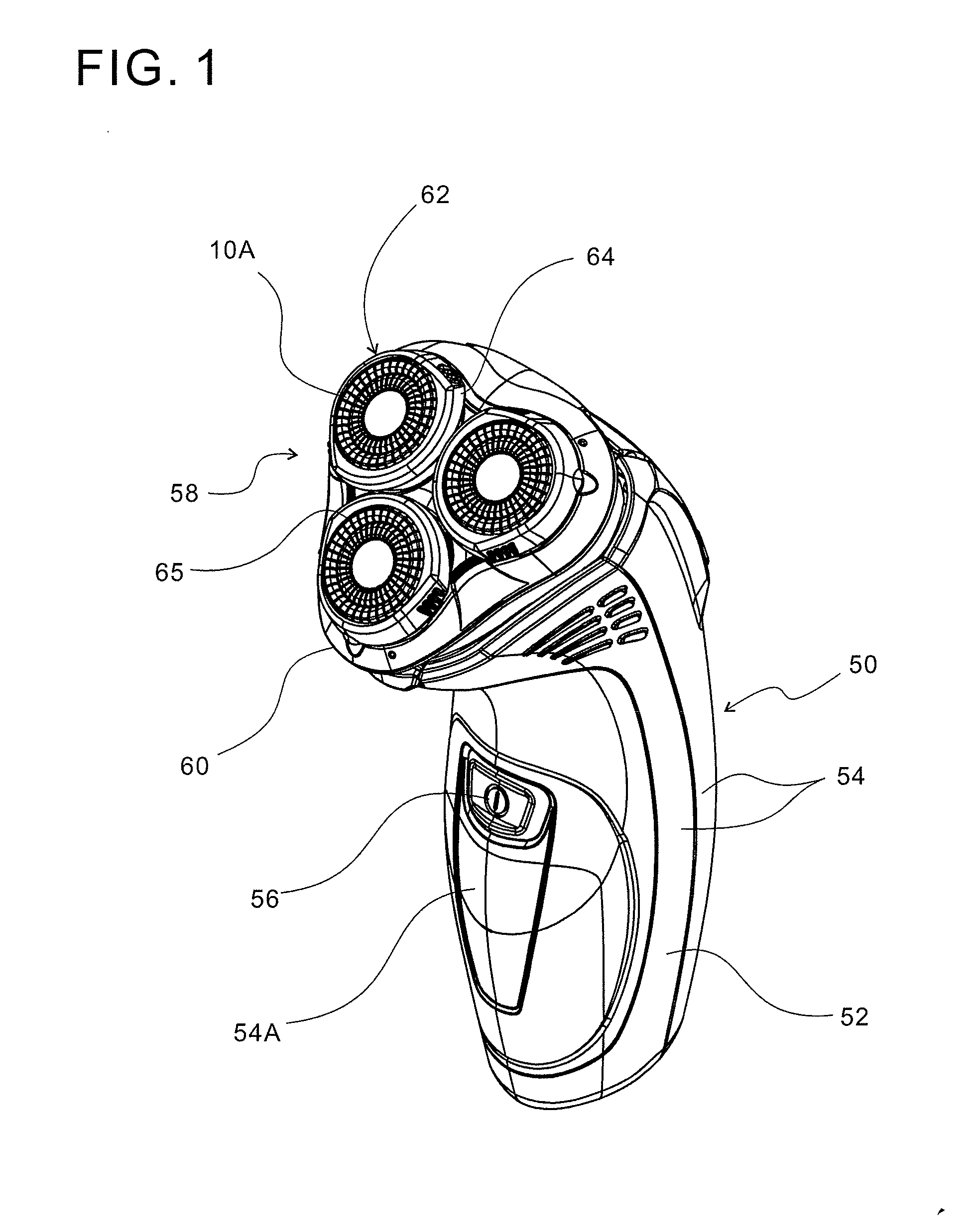
[0034]Referring to FIG. 1, a main body 50 has a case 54 formed by curving an upper portion of a grip 52, which is approximately columnar, diagonally upward to the front. The case 54, which can be split into a front counterpart and a back counterpart, houses a chargeable battery, an electric motor, a control circuit board and the like (not shown). A power switch 56 is attached to the front surface of the case 54. A display (not shown) composed of LED lamps indicating the amount of remaining charge of the battery, an operation status and the like is located under the switch 56. The display can be seen from outside through a translucent portion 54A of the case 54.

[0035]A head unit 58 is openably and detachably attached to an upper portion of the case 54. The head unit 58 is inclined relative to the grip 52 of the case 54 such that the shaving sections (the upper surface of a cutter frame 60, which will hereinafter be described in detail) are directed diagonally upward to the front. The...


PUM

PropertyMeasurementUnit
heightsaaaaaaaaaa
areaaaaaaaaaaa
areasaaaaaaaaaa

Abstract

A rotary electric shaver includes an outer cutter having an upper surface with annular shaving sections, formed with hair entry apertures, and an inner cutter having small blades, which rotate in sliding contact with the outer cutter from below the shaving sections. The outer cutter has a plurality of concentric annular shaving sections. The shaving section adjacent to an outer periphery is lower than the shaving section adjacent to a center. The shaving sections are formed on a plane horizontal to a central axis. This makes it possible to increase a shaving area, to precisely trace the curved surface of a concave portion of skin and to come in contact with the skin with a proper contact pressure, thus permitting smooth shaving of the concave portion. The shaver has a simple structure with a smaller number of components, featuring easier assembly and easier removal of hair bits.

Description

BACKGROUND OF THE INVENTION[0001]1. Field of the Invention[0002]The present invention relates to a rotary electric shaver and, more particularly, to a rotary electric shaver having an outer cutter which has annular shaving faces or sections with many hair entry apertures formed therein and an inner cutter having small blades which rotate in sliding contact with the outer cutter from below the shaving section. The present invention also relates to a manufacturing method of the outer cutter and the inner cutter used with the rotary electric shaver.[0003]2. Description of the Related Art[0004]This type of rotary electric shaver is required to be capable of enabling approximately disc-shaped outer cutters to minutely trace the fine irregularities in the skin surface to smoothly shave beard without leaving any unshaved places. For example, there is a problem in that chances of leaving unshaved areas tend to increase in a markedly uneven skin surface, such as an area below the jaw of a us...

Claims


Application Information

Patent Timeline
Patent Type & Authority Applications(United States)
IPC IPC(8): B26B19/14B23P17/00B23P15/16
CPCB26B19/143Y10T29/49Y10T29/496
Inventor MIMURA, YOSHIYUKI
Owner IZUMI PROD CO
Why Eureka
Try Eureka