Supercharge Your Innovation With Domain-Expert AI Agents!

Image Combining Apparatus and Image Combining Program

a technology of image combining apparatus and program, which is applied in the field of image combining apparatus and image combining program, can solve the problems of not being easy in the conventional art to produce a combined imag

Active Publication Date: 2012-05-10
KONICA MINOLTA BUSINESS TECH INC
View PDF2 Cites 17 Cited by
  • Summary
  • Abstract
  • Description
  • Claims
  • Application Information

AI Technical Summary

Benefits of technology

[0006]The present invention has been achieved taking the aforementioned problems into consideration. A main object of the present invention therefore is to provide an image combining apparatus and image combining program that can easily produce a combined image at a prescribed position of a sheet or screen.

Problems solved by technology

Thus, it has not been easy in the conventional art to produce a combined image.

Method used


Image

  • Image Combining Apparatus and Image Combining Program
  • Image Combining Apparatus and Image Combining Program
  • Image Combining Apparatus and Image Combining Program

Examples


example 1

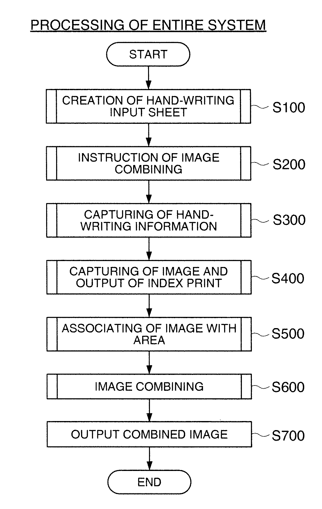
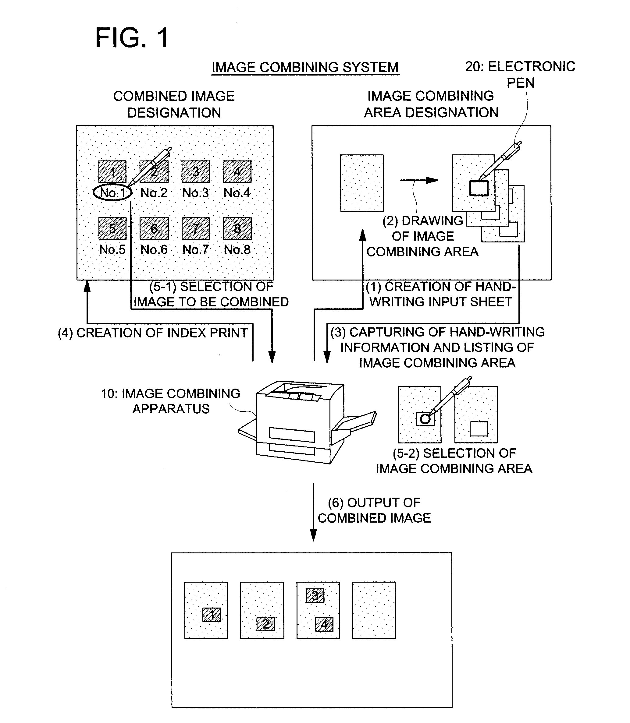
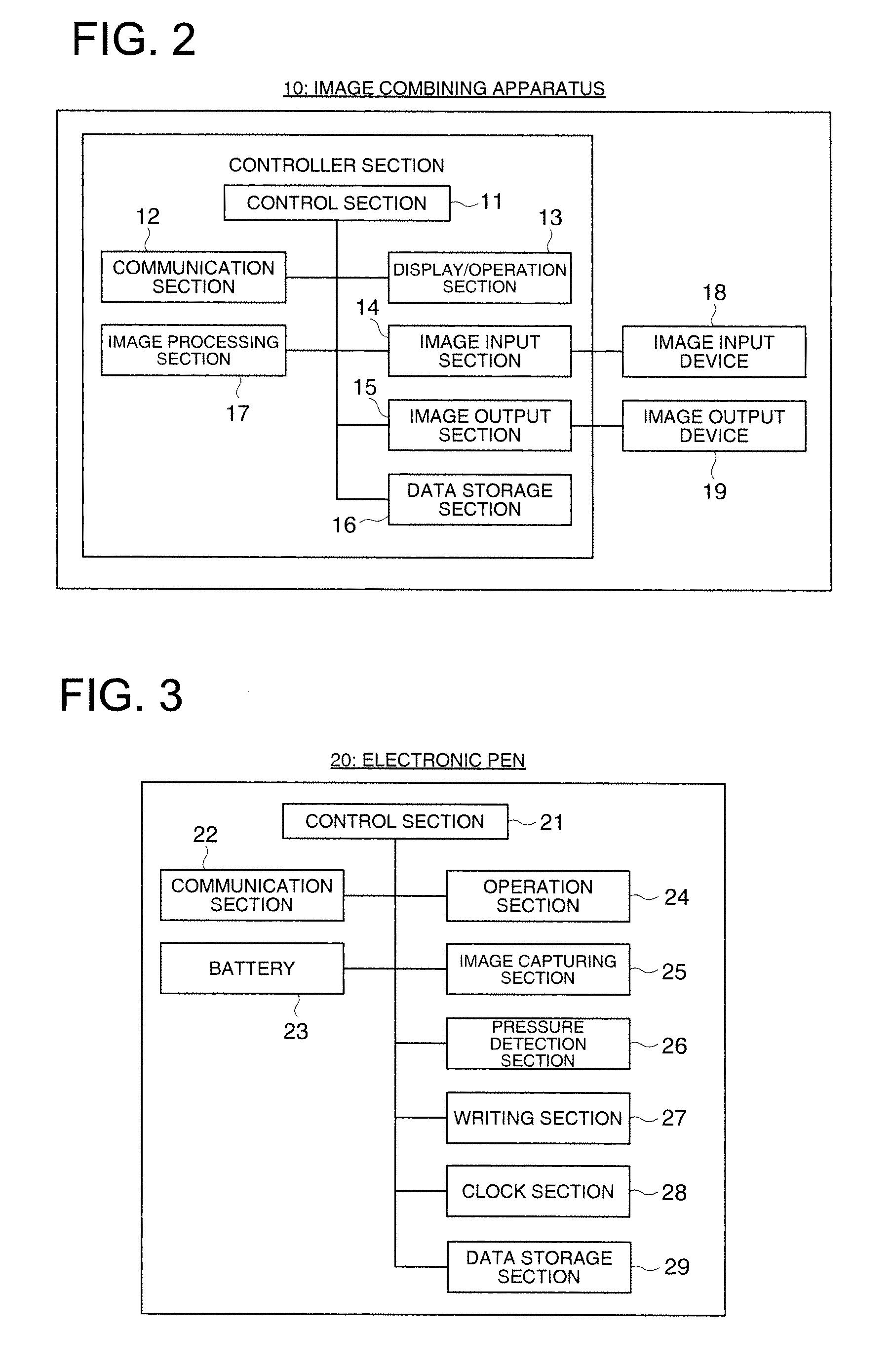
[0040]To give a further detailed description of the aforementioned embodiment of the present invention, the following describes the image combining apparatus and image combining program in the first Example of the present invention, with reference to FIGS. 1 through 15. FIG. 1 is a diagram representing the structure and outline of operation of an image combining system in the first Example. FIG. 2 is a block diagram representing the structure of the image combining apparatus. FIG. 3 is a block diagram showing the structure of an electronic pen. FIG. 4 is a diagram showing an example of the Anoto (registered trademark) pattern. FIGS. 5, 6, 8, 10 through 12 and 14 are flow charts showing the processing of the image combining system. FIGS. 7, 9, 13 and 15 are drawings illustrating the processing in the image combining system.

[0041]As shown in FIG. 1, the image combining system of the present Example includes an image combining apparatus 10 in which combining of the images of such objec...

example 2

[EXAMPLE 2]

[0099]Referring to FIGS. 16 through 19, the following describes the image combining apparatus and image combining program in a second Example of the present invention. FIG. 16 is a diagram showing the structure and outline of operation of the image combining system in the present Example. FIG. 17 is a flow chart showing the overall processing of the image combining system. FIG. 18 is a flow chart showing the processing of associating an image with an area. FIG. 19 is a diagram describing the process of associating an image with an area.

[0100]In the aforementioned first Example, an image combining area is drawn on the handwriting input sheet, and an image combining instruction information list is created. After that, an image is selected on the index print, and the image combining area is selected on the handwriting input sheet having an image combining area drawn in advance. However, it is also possible to omit the processes of drawing an image combining area on the handw...


PUM


Abstract

An image combining apparatus includes a control section which acquires first position information identifying a figure on a first medium from an electronic pen by using the first medium where a pattern for the electronic pen to detect an electronic pen tip position is combined with a background of a image list, identifies an image from the position information by referring to information associating each image with a position on the first medium, further acquires second position information identifying a figure on a second medium from the electronic pen by using the second medium on which the pattern is formed, and identifies an image combining area from the first and second position information, and then associates the image combining area with the image; and an image processing section creating a combined image by combining the image combining area with the image associated with the image combining area.

Description

[0001]This application is based on Japanese Patent Application No. 2010-251998 filed on Nov. 10, 2010 with Japanese Patent Office, the entire content of which is hereby incorporated by reference.BACKGROUND OF THE INVENTION[0002]The present invention relates to an image combining apparatus and image combining program, particularly to an image combining apparatus and image combining program that use an electronic pen to combine images.[0003]One of the input devices used in recent years is an electronic pen by which handwriting is inputted by a pen and then outputted as handwriting data. This electronic pen has a small-sized camera mounted on the pen tip. The small-sized camera is used to read a position detection pattern called the Anoto (registered trademark) pattern printed on a sheet, thereby identifying the position of the pen tip and outputting handwriting such as a handwritten character, figures and pictures as handwriting data.[0004]An example of a system using such an electron...

Claims


Application Information

Patent Timeline
Patent Type & Authority Applications(United States)
IPC IPC(8): G06K9/18G06V30/224G06F3/048G06V30/10
CPCG06T11/60G06K2009/226G06K9/2081G06V30/10G06V30/1426G06V30/1456
Inventor FUJIWARA, YOKO
Owner KONICA MINOLTA BUSINESS TECH INC
Features
  • R&D
  • Intellectual Property
  • Life Sciences
  • Materials
  • Tech Scout
  • Unparalleled Data Quality
  • Higher Quality Content
  • 60% Fewer Hallucinations
Learn More