Image processing device and image processing method

a technology of image processing and image data, applied in image enhancement, instruments, computing, etc., can solve the problems of not handling code amounts (bit rates) lower than mpeg1, encoding formats with even higher compression rates, and it is difficult to transmit two screens worth of image data. , to achieve the effect of improving the encoding efficiency of prediction encoding of images

Inactive Publication Date: 2012-05-10
SONY CORP
View PDF2 Cites 28 Cited by
  • Summary
  • Abstract
  • Description
  • Claims
  • Application Information

AI Technical Summary

Benefits of technology

[0080]According to the first and second aspects of the present inventio

Problems solved by technology

MPEG2 was primarily for high image quality encoding suitable for broadcasting, but did not handle code amounts (bit rate) lower than MPEG1, i.e., encoding formats with even higher compression rates.
However, depending on the transmission band of a transmission path for transmitting the 3D image, stor

Method used


Image

  • Image processing device and image processing method
  • Image processing device and image processing method
  • Image processing device and image processing method

Examples


first embodiment

[Embodiment of Encoding Device]

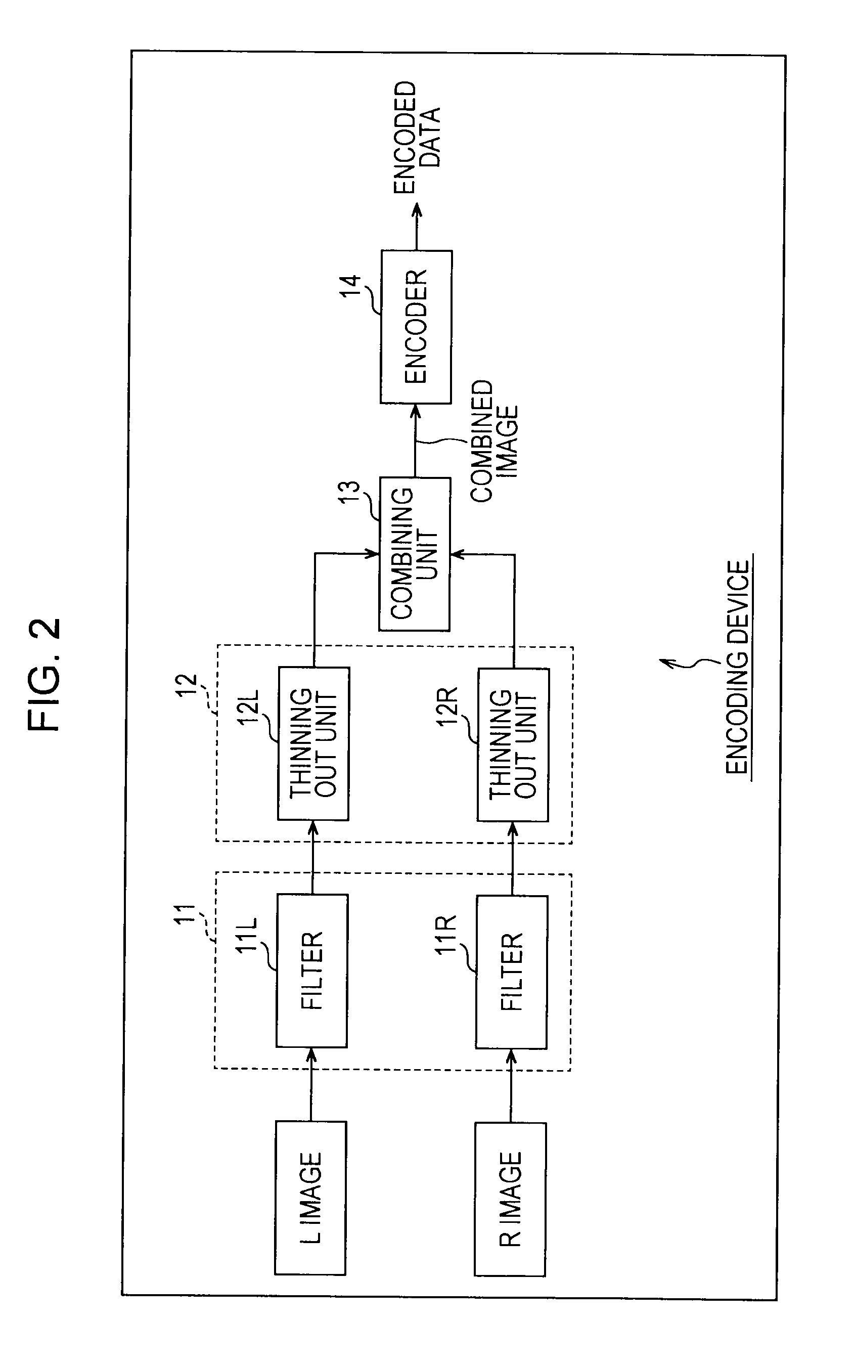
[0116]FIG. 5 is a block diagram illustrating the configuration of an embodiment of a encoding device to which an image processing device according to the present invention has been applied.

[0117]In FIG. 5, the portions corresponding to the encoding device shown in FIG. 2 are denoted with the same reference numerals, and in the following, description thereof will be omitted as appropriate.

[0118]That is to say, the encoding device in FIG. 5 is the same as with the case in FIG. 2 regarding the point of having a filter unit 11 and thinning out unit 12.

[0119]Note however, that the encoding device in FIG. 5 differ from the case in FIG. 2 regarding the point of having a horizontal processing unit 31, a vertical processing unit 32, and a control unit 35. Further, the encoding device in FIG. 5 has, instead of the combining unit 13 and encoder 14, a combining unit 33 and encoder 34, respectively, which is a point also different from the case in FIG. 2.

[0120]The ...

second embodiment

[Another Embodiment of Encoding Device]

[0392]FIG. 19 is a block diagram illustrating a configuration example of another embodiment of an encoding device to which the image processing device according to the present invention has been applied.

[0393]In FIG. 19, portions corresponding to the encoding device in FIG. 5 are denoted with the same reference numerals, and description thereof will be omitted as appropriate.

[0394]That is to say, the encoding device 19 has in common with the case in FIG. 5 in the point of having an encoder 34.

[0395]Note however, that the encoding device in FIG. 19 differs from the case in FIG. 5 in the point of having imaging apparatuses 101L and 101R. Further, the encoding device in FIG. 19 differs from the case in FIG. 5 in the point of having a synthesizing unit 102 instead of the filter unit 11, thinning-out unit 12, horizontal processing unit 31, vertical processing unit 32, combining unit 33, and control unit 35.

[0396]With the encoding device in FIG. 5 de...


PUM


Abstract

The present invention relates to an image processing device and an image processing method whereby encoding efficiency of image prediction encoding can be improved.
A horizontal processing unit 31 performs horizontal packing as horizontal processing to manipulate the horizontal-direction array of pixels of each of a first thinned-out image and a second thinned-out image arrayed in checkerboard fashion, obtained by thinning out the pixels of each of a first image and a second image different from the first image every other line in an oblique direction, wherein pixels of first and second thinned-out images are packed in the horizontal direction. A combining unit 33 generates a combined image which is combined by adjacently arraying the post-horizontal processing first and second thinned-out images after horizontal processing, as an image to serve as the object of prediction encoding. The present invention can be applied to a case of performing prediction encoding on a first and second image, such as an L (Left) image and R (Right) image making up a 3D image or the like, for example.

Description

TECHNICAL FIELD[0001]The present invention relates to an image processing device and an image processing method, and more particularly relates to an image processing device and an image processing method whereby, for example, encoding efficiency of prediction encoding of an image can be improved.BACKGROUND ART[0002]As of recent, there have come into widespread use, both for information distribution such as broadcasting stations and information reception in general homes, devices which conform to formats such as MPEG (Moving Picture Expert Group) which uses redundancy which is characteristic to image information and perform compression by orthogonal transform such as discreet cosine transform and the like and motion compensation, in order to transmit and store information with high efficiency when handling image information as digital signals.[0003]That is to say, there is coming into widespread use encoding devices and decoding devices used for processing performed when receiving im...

Claims


Application Information

Patent Timeline
IPC IPC(8): G06K9/36G09G5/00G09G5/36G09G5/377H04N1/387H04N13/00H04N19/132H04N19/162H04N19/172H04N19/423H04N19/46H04N19/50H04N19/503H04N19/59H04N19/593H04N19/597H04N19/60H04N19/61H04N19/70H04N19/80H04N19/82H04N19/85H04N19/91
CPCH04N13/0029H04N13/0048H04N19/59H04N19/597H04N19/85H04N13/004H04N13/156H04N13/161H04N13/139H04N13/00G06T5/30G09G5/377
Inventor TAKAHASHI, YOSHITOMOSUZUKI, TERUHIKOKITAMURA, TAKUYAYAGASAKI, YOICHI
Owner SONY CORP
Why Eureka
Try Eureka